Table of Contents
Advertisement
Quick Links
Advertisement
Table of Contents

Subscribe to Our Youtube Channel
Related Manuals for Baumer Hubner Berlin HOG 86 + DSL


Summary of Contents for Baumer Hubner Berlin HOG 86 + DSL
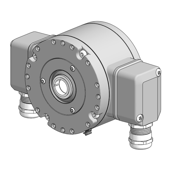
- Page 1 Montage- und Betriebsanleitung Mounting and operating instructions HOG 86 + DSL Kombination Inkrementaler Drehgeber mit integriertem programmierbaren, digitalen Drehzahlschalter Combination Incremental encoder with integrated programmable, digital speed switch...
- Page 2 Inhaltsverzeichnis Inhaltsverzeichnis Allgemeine Hinweise Abmessungen ......................Sicherheitshinweise Kombination ....................... Montagemöglichkeiten Vorbereitung ......................Stützbleche (Zubehör) Lieferumfang ..................... Elektrischer Anschluss Zur Montage erforderlich ........(nicht im Lieferumfang enthalten) HOG 86 ..................Montagesets zur Befestigung einer 6.1.1 Montage Anschlusskabel ......
-
Page 3: Table Of Contents
Table of contents Table of contents General notes Dimensions ............................ Security indications Combination ....................... Mounting possibilities Preparation ....................... Support plates (accessories) Scope of delivery ................Electrical connection Required for mounting ..........(not included in scope of delivery) HOG 86 .... - Page 4 Gebrauchte Elektro- und Elektronikgeräte dürfen nicht im Hausmüll entsorgt werden. Das Produkt enthält wertvolle Rohstoffe, die recycelt werden können. Wenn immer möglich sollen Altgeräte lokal am entsprechenden Sammeldepot entsorgt werden. Im Bedarfsfall gibt Baumer den Kunden die Möglichkeit, Baumer-Produkte fachgerecht zu entsor- gen. Weitere Informationen siehe www.baumer.com. Achtung! Beschädigung des auf dem Gerät befindlichen Siegels...
-
Page 5: General Notes
Whenever possible, waste electrical and electronic equipment should be disposed locally at the authorized collection point. If necessary, Baumer gives customers the opportunity to dispose of Baumer products profession- ally. For further information see www.baumer.com. - Page 6 Sicherheitshinweise Sicherheitshinweise Verletzungsgefahr durch rotierende Wellen Haare und Kleidungsstücke können von rotierenden Wellen erfasst werden. • Vor allen Arbeiten alle Betriebsspannungen ausschalten und Maschinen stillsetzen. Zerstörungsgefahr durch elektrostatische Aufladung Die elektronischen Bauteile im Gerät sind empfindlich gegen hohe Spannungen. • Steckkontakte und elektronische Komponenten nicht berühren. •...
-
Page 7: Security Indications
Security indications Security indications Risk of injury due to rotating shafts Hair and clothes may become tangled in rotating shafts. • Before all work switch off all voltage supplies and ensure machinery is stationary. Risk of destruction due to electrostatic charge Electronic parts contained in the device are sensitive to high voltages. -
Page 8: Preparation
Vorbereitung / Preparation Vorbereitung Preparation Lieferumfang Scope of delivery Gehäuse Housing Einseitig offene Hohlwelle mit Schlüsselfläche Blind hollow shaft with spanner flat SW 17 mm 17 mm a/f Spannelement Clamping element Abdeckhaube mit O-Ring Cover with o-ring Ejot-Schraube M4x14 mm Ejot screw M4x14 mm Schraube M4x6 mm für Erdungsband, Screw M4x6 mm for earthing strap, ISO 1207 ISO 1207 Scheibe A4,3 für Erdungsband, ISO 7090 Washer A4.3 for earthing strap, ISO 7090... -
Page 9: Required For Mounting (Not Included In Scope Of Delivery)
Vorbereitung / Preparation Zur Montage erforderlich Required for mounting (nicht im Lieferumfang enthalten) (not included in scope of delivery) Montageset Erdungsband als Zubehör erhältlich: Mounting kit earthing strap available as ac- Bestellnummer 11071906, bestehend aus ... cessory: Order number 11071906, including ... Erdungsband, Länge ~230 mm Earthing strap, length ~230 mm Zylinderschraube M6x8 mm, ISO 1207... -
Page 10: Mounting Kits To Fix A Torque Arm At The Device
Vorbereitung / Preparation Montagesets zur Befestigung einer Mounting kits to fix a torque arm at the Drehmomentstütze an das Gerät device (nicht im Lieferumfang enthalten) (not included in scope of delivery) 20e 20c Stützblech-Montageset R63 für Drehmoment- Support plate mounting kit R63 for torque arm stütze Größe M6, als Zubehör erhältlich: size M6, available as accessory: Bestellnummer 11071850, bestehend aus ... -
Page 11: Mounting Kit To Fix A Torque Arm On The Drive Side (Not Included In Scope Of Delivery)
Vorbereitung / Preparation Montageset zur Befestigung einer Mounting kit to fix a torque arm on Drehmomentstütze an der Antriebssei- the drive side (not included in scope of te (nicht im Lieferumfang enthalten) delivery) Montageset für Drehmomentstütze Größe M6, Mounting kit for torque arm size M6, available als Zubehör erhältlich: as accessory: Bestellnummer 11071904, bestehend aus ... -
Page 12: Mounting
Montage / Mounting Montage Mounting Wir empfehlen, das Gerät so zu It is recommended to mount the device montieren, dass der Kabelanschluss with cable connection facing down- keinem direkten Wassereintritt ward and being not exposed to water. ausgesetzt ist. Entfernen der Abdeckhaube Remove the cover 3 mm Montage mit Stützblech... -
Page 13: Additional Mounting Examples
Montage / Mounting 4.2.1.2 Weitere Montagebeispiele 4.2.1.2 Additional mounting examples (6 Positionen möglich) (6 positions possible) MB194.3 - 11173626 Baumer_HOG86-DSL_II_DE-EN (19A2) -
Page 14: Mounting The Torque Arm At The Support Plate
Montage / Mounting Montage mit Stützblech Mounting with support plate (Zubehör) (accessory) 4.2.2 Montage der Drehmomentstütze am 4.2.2 Mounting the torque arm at the support Stützblech plate Variante 1 10 mm Mit angeschweißter Mutter With welded-on nut 10 mm 10 mm Variante 2 10 mm 10 mm... -
Page 15: Mounting To Drive Shaft
Montage / Mounting 4.2.3 Montage an Antriebswelle 4.2.3 Mounting to drive shaft 10 mm 17 mm 5 mm Zentrierbohrung Center hole DIN 332-D, 14b 14a M6x16 mm Zul. Anzugsmoment: Max. tightening torque: = 6 Nm 52 (40...52) Alle Abmessungen in Millimeter (wenn nicht anders angegeben) * Siehe Seite 5, 6 oder 8 All dimensions in millimeters (unless otherwise stated) See page 5, 6 or 8... -
Page 16: Drive Side Mounting Of The Torque Arm
Montage / Mounting Montage mit Stützblech Mounting with support plate (Zubehör) (accessory) 4.2.4 Antriebsseitige Montage der Drehmo- 4.2.4 Drive side mounting of the torque arm mentstütze Die Montage der Drehmomentstütze The torque arm should be mounted sollte spielfrei erfolgen. Ein Spiel von free from clearance. -
Page 17: Mounting With Screw Mounting Kit (Accessory)
Montage / Mounting Montage mit Schraubmontageset Mounting with screw mounting kit (Zubehör) (accessory) 4.3.1 Montage der Drehmomentstütze an 4.3.1 Mounting the torque arm at the device das Gerät 4.3.1.1 Mounting example 4.3.1.1 Montagebeispiel 4 mm * Siehe Seite 5, 6 oder 7 1.6x8 mm See page 5, 6 or 7 4.3.1.2... -
Page 18: Mounting To Drive Shaft
Montage / Mounting Montage mit Schraubmontageset Mounting with screw mounting kit (Zubehör) (accessory) 4.3.2 Montage an Antriebswelle 4.3.2 Mounting to drive shaft 10 mm 17 mm 5 mm Zentrierbohrung Center hole DIN 332-D, 14b 14a M6x16 mm Zul. Anzugsmoment: Max. tightening torque: = 6 Nm 52 (40...52) Alle Abmessungen in Millimeter (wenn nicht anders angegeben) -
Page 19: Drive Side Mounting Of The Torque Arm
Montage / Mounting 4.3.3 Antriebsseitige Montage der Drehmo- 4.3.3 Drive side mounting of the torque arm mentstütze L2 (≥L1) Die Montage der Drehmomentstütze The torque arm should be mounted sollte spielfrei erfolgen. Ein Spiel von free from clearance. A play of just beispielsweise ±0,03 mm entspricht ±0.03 mm, results in a runout of the einem Rundlauffehler des Gerätes von... -
Page 20: How To Prevent Measurement Errors
Montage / Mounting Hinweis zur Vermeidung von Messfeh- How to prevent measurement errors lern Für einen einwandfreien Betrieb des To ensure that the device operates cor- Gerätes ist eine korrekte Montage, ins- rectly, it is necessary to mount it accu- besondere auch der Drehmomentstütze, rately as described in section 4.2 / 4.3, notwendig, wie beschrieben in Abschnitt... -
Page 21: Fix The Cover
Montage / Mounting Abdeckhaube befestigen Fix the cover Zul. Anzugsmoment Max. tightening torque = 2...3 Nm 3 mm * Siehe Seite 5 See page 5 MB194.3 - 11173626 Baumer_HOG86-DSL_II_DE-EN (19A2) -
Page 22: Mounting Possibilities
Abmessungen / Dimensions Abmessungen Dimensions Kombination Combination (73455) (73455) Positive Drehrichtung Positive rotating direction Montagemöglichkeiten Mounting possibilities Alle Abmessungen in Millimeter (wenn nicht anders angegeben) * Siehe Seite 7 All dimensions in millimeters (unless otherwise stated) See page 7 MB194.3 - 11173626 Baumer_HOG86-DSL_II_DE-EN (19A2) -
Page 23: Support Plates (Accessories)
Abmessungen / Dimensions Stützbleche (Zubehör) Support plates (accessories) Alle Abmessungen in Millimeter (wenn nicht anders angegeben) * Siehe Seite 7 All dimensions in millimeters (unless otherwise stated) See page 7 MB194.3 - 11173626 Baumer_HOG86-DSL_II_DE-EN (19A2) -
Page 24: Hog
Elektrischer Anschluss / Electrical connection Elektrischer Anschluss Electrical connection HOG 86 HOG 86 6.1.1 Montage Anschlusskabel 6.1.1 Mounting connecting cable TX 20 10 * 22 mm 11 * Zul. Anzugsmoment Max. tightening torque = 2...3 Nm Kabelschirm Cable shield Ansicht X siehe Abschnitt 6.1.3. View X see section 6.1.3. -
Page 25: Terminal Significance
Elektrischer Anschluss / Electrical connection 6.1.2 Beschreibung der Anschlüsse 6.1.2 Terminal significance Betriebsspannung +UB; + Voltage supply Masseanschluss ; ; GND; 0V Ground Erdungsanschluss (Gehäuse) Earth ground (housing) Ausgangssignal Kanal 1 K1; A; A+ Output signal channel 1 Ausgangssignal Kanal 1 invertiert K1; A; A- Output signal channel 1 inverted Ausgangssignal Kanal 2 (90°... - Page 26 Sensorkabel HEK 8 (Zubehör) 6.1.5 Sensor cable HEK 8 (accessory) Es wird empfohlen, das Baumer Hübner Baumer Hübner sensor cable HEK 8 is Sensorkabel HEK 8 zu verwenden oder recommended. As a substitute a shielded ersatzweise ein geschirmtes, paarig ver- twisted pair cable should be used.
-
Page 27: Dsl
Elektrischer Anschluss / Electrical connection 6.2.1 Montage Anschlusskabel 6.2.1 Mounting connecting cable TX 20 10 * 22 mm Zul. Anzugsmoment Max. tightening torque 12 * = 2...3 Nm Kabelschirm Cable shield Ansicht Y siehe Abschnitt 6.2.2. View Y see section 6.2.2. ø7...12 mm * Siehe Seite 5 oder 6 See page 5 or 6 Zur Gewährleistung der angegebenen To ensure the specified protection of... - Page 28 RS 485 Schnittstelle für PC oder Laptop (Adapter erforderlich). Interface for PC or Laptop (adapter required). Programmierung des DSL über Software zum Download unter www.baumer.com: Software für Windows XP Benutzerhandbuch für Windows XP Software für Windows 7-10 Benutzerhandbuch für Windows 7-10 Programming of the DSL via software available for download at www.baumer.com:...
-
Page 29: Block Diagramm
Elektrischer Anschluss / Electrical connection 6.2.3 Blockschaltbild 6.2.3 Block diagramm Kombination/Combination 15...30 VDC High = 12 V, Low = 0 V HOG 86 0 V (GND) RS 485 für/for PC/Laptop A, B 0 V (GND) 6.2.4 Ausgangsschaltverhalten 6.2.4 Switching characteristics 12 VDC 1,2,3 0 V (GND) -ns off -ns on... -
Page 30: Ds 93 R
Elektrischer Anschluss / Electrical connection 6.2.5 DS 93 R 6.2.5 DS 93 R Relaismodul (Zubehör) relay modul (accessory) 6.2.5.1 Klemmenbelegung 6.2.5.1 Terminal assignment 3 Kontroll-LED‘s Höhe = 55 mm 3 control LEDs Kunststoffgehäuse für Tragschienenmontage (EN 50022) IP 20 Height = 55 mm 3 Relais/relays Plastic housing for ≤6 A / 250 VAC... -
Page 31: Dismounting
Demontage / Dismounting Demontage Dismounting Schritt 1 Step 1 12 * TX 20 10 * 22 mm * Siehe Seite 5 oder 6 See page 5 or 6 MB194.3 - 11173626 Baumer_HOG86-DSL_II_DE-EN (19A2) - Page 32 Demontage / Dismounting Schritt 2 Step 2 11 * TX 20 10 * 22 mm * Siehe Seite 5 oder 6 See page 5 or 6 MB194.3 - 11173626 Baumer_HOG86-DSL_II_DE-EN (19A2)
- Page 33 Demontage / Dismounting Schritt 3 Step 3 3 mm Schritt 4 Step 4 10 mm 1.6x8 mm * Siehe Seite 5, 6 oder 8 See page 5, 6 or 8 MB194.3 - 11173626 Baumer_HOG86-DSL_II_DE-EN (19A2)
- Page 34 Demontage / Dismounting Schritt 5 Step 5 17 mm 5 mm Schritt 6 Step 6 0.8x4 mm * Siehe Seite 6 oder 8 See page 6 or 8 MB194.3 - 11173626 Baumer_HOG86-DSL_II_DE-EN (19A2)
- Page 35 Demontage / Dismounting Schritt 7 Step 7 17 mm 6 mm Schritt 8 Step 8 * Siehe Seite 8 See page 8 MB194.3 - 11173626 Baumer_HOG86-DSL_II_DE-EN (19A2)
- Page 36 Technische Daten Technische Daten Technische Daten - elektrisch • Betriebsspannung: 15...30 VDC • Betriebsstrom ohne Last: ≤200 mA • Störfestigkeit: EN 61000-6-2 • Störaussendung: EN 61000-6-3 • Zulassung: Technische Daten - elektrisch (Drehgeber) • Impulse pro Umdrehung: 512, 1024, 2048 oder 2500 (je nach Bestellung) •...
- Page 37 Technische Daten - mechanisch • Baugröße (Flansch): ø99 mm • Wellenart: ø16 mm (einseitig offene Hohlwelle) • Zulässige Wellenbelastung: ≤350 N axial ≤450 N radial • Schutzart DIN EN 60529: IP66 • Drehzahl (n): ≤6000 U/min (mechanisch) • Schaltdrehzahlbereich (ns): Impulszahl = 512: ±16...6000 U/min Impulszahl = 1024: ±8...6000 U/min...
-
Page 38: Technical Data
Technical data Technical data Technical data - electrical ratings • Voltage supply: 15...30 VDC • Consumption w/o load: ≤200 mA • Interference immunity: EN 61000-6-2 • Emitted interference: EN 61000-6-3 • Approval: Technical data - electrical ratings (encoder) • Pulses per revolution: 512, 1024, 2048 or 2500 (as ordered) •... -
Page 39: Technical Data - Mechanical Design
Technical data - mechanical design • Size (flange): ø99 mm • Shaft type: ø16 mm (blind hollow shaft) • Admitted shaft load: ≤350 N axial ≤450 N radial • Protection DIN EN 60529: IP66 • Speed (n): ≤6000 rpm • Range of switching speed (ns ): Pulses = 512: ±16...6000 rpm Pulses = 1024: ±8...6000 rpm Pulses = 2048:... - Page 40 • Relay modul DS 93 R 3 x Umschalter 3 x Change-over switch (≤6 A/250 VAC, ≤1 A/48 VDC) (≤6 A/250 VAC, ≤1 A/48 VDC) • Software zum Download unter • Software for download at www.baumer.com www.baumer.com • DSL-Benutzerhandbuch zum • DSL user manual for download at Download unter www.baumer.com www.baumer.com Für HOG 86...
- Page 41 MB194.3 - 11173626 Baumer_HOG86-DSL_II_DE-EN (19A2)
- Page 42 MB194.3 - 11173626 Baumer_HOG86-DSL_II_DE-EN (19A2)
- Page 43 MB194.3 - 11173626 Baumer_HOG86-DSL_II_DE-EN (19A2)
- Page 44 Baumer Hübner GmbH P.O. Box 12 69 43 · 10609 Berlin, Germany Phone: +49 (0)30/69003-0 · Fax: +49 (0)30/69003-104 info@baumerhuebner.com · www.baumer.com/motion Version: 73455 MB194.3 - 11173626 Baumer_HOG86-DSL_II_DE-EN (19A2-06.11.2019)
Need help?
Do you have a question about the Hubner Berlin HOG 86 + DSL and is the answer not in the manual?
Questions and answers