
Related Manuals for Velleman High-Q Kit K1803


Summary of Contents for Velleman High-Q Kit K1803
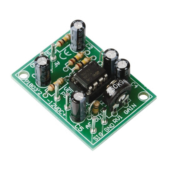
- Page 1 Total solder points: 29 Difficulty level: beginner 1 advanced UNIVERSAL MONO PREAMPLIFIER K1803 ILLUSTRATED ASSEMBLY MANUAL H1803IP-1...
-
Page 2: Specifications
Features & Specifications SPECIFICATIONS: Power supply: 10-30VDC / 10mA. Output impedance: 1Kohm. Adjustable output level: max. 40dB. Frequency range: 20Hz to 20kHz ± 3dB. Max. input signal: 40mV. PCB dimensions: 30 x 44mm (1.2" x 1.7"). -
Page 3: Assembly Hints
Assembly hints 1. Assembly (Skipping this can lead to troubles ! ) Ok, so we have your attention. These hints will help you to make this project successful. Read them carefully. 1.1 Make sure you have the right tools: • A good quality soldering iron (25-40W) with a small tip. - Page 4 REMOVE THEM FROM THE TAPE ONE AT A TIME ! AXIAL COMPONENTS ARE TAPED IN THE CORRECT MOUNTING SEQUENCE ! You will find the colour code for the resistances and the LEDs in the HALG (general manual) and on our website: http://www.velleman.be/common/service.aspx...
- Page 5 Construction 1. Resistors 3. Electrolytic capacitors. 6. IC mounting Watch the polarity ! IC1 : UA741M C... R... C1 : 10µF C2 : 1µF C3 : 1µF Pay attention to the position of the notch! R1 : 2K2 (2 - 2 - 2 - B) 4.
- Page 6 Connection 7. Connection Connect a stabilized supply between 10 and 30V with the points “+” and “-” on the print. The input is connected on the points “AF IN”. The output is taken between the outer right connection “AF OUT” and the mass “-”. To connect your in–...
- Page 7 Schematic diagram & PCB 8. Schematic diagram. 9. PCB 220K AF IN 1µF AF OUT 10µF 1µF AF IN AF OUT...
- Page 8 VELLEMAN Components NV Legen Heirweg 33 9890 Gavere Belgium Europe www.velleman.be www.velleman-kit.com Modifications and typographical errors reserved © Velleman Components nv. H1803IP - 2004 - ED1 (rev1) 5 4 1 0 3 2 9 3 1 0 3 1 8...
- Page 9 Largest Supplier of Electrical and Electronic Components Click to view similar products for manufacturer: Velleman Other Similar products are found below : MK137 MK106 K2622 K/DIODE1 72-6514 MK108 K8072 K2634 80-7352 K/TF300 MK149 HPS140MK2 VM100 MK123 MK144 MK152 K8086 K/RES-E12 MK190 MK134 K/TRANS1 CD018 K1803 K/RES-E3 MK111 MK103 MK100 OMSB36 K/CAP1 MK109...
Need help?
Do you have a question about the High-Q Kit K1803 and is the answer not in the manual?
Questions and answers