
Related Manuals for Velleman K8066


Summary of Contents for Velleman K8066
- Page 1 Total solder points: 34 Difficulty level: beginner 1 advanced 3W MONO AMPLIFIER K8066 ILLUSTRATED ASSEMBLY MANUAL H8066IP-1...
-
Page 3: Specifications
Features & Specifications Specifications: Compact size. Low partcount. No additional heatsink required. Single supply. Wide supply range. Excellent protection Features: Output power : 3Wrms (4-8 ohm, 15VDC, 10%THD). Freq. Range : 50Hz—20KHz (1W/8ohm/-3dB). Gain : 32dB ( 40x). Thermal protection. Short circuit protection. -
Page 4: Assembly Hints
Assembly hints 1. Assembly (Skipping this can lead to troubles ! ) Ok, so we have your attention. These hints will help you to make this project successful. Read them carefully. 1.1 Make sure you have the right tools: • A good quality soldering iron (25-40W) with a small tip. - Page 5 Assembly hints 1.3 Soldering Hints : 1- Mount the component against the PCB surface and carefully solder the leads 2- Make sure the solder joints are cone-shaped and shiny 3- Trim excess leads as close as possible to the solder joint...
-
Page 6: Electrolytic Capacitors
Construction 1. Diodes. Watch the polarity ! 5. Electrolytic Capacitors. 3. Capacitor. Watch the polarity ! C... C3 : 100µF D... CATHO DE C4 : 47µF C... C5 : 470µF C1 : 100nF (104) D1 : 1N4007 C2 : 100nF (104) 2. - Page 7 OUT-. You can adjust the volume by mounting a potentiometer of e.g. 47K log. in front of the input of the K8066 (fig. 1.0). Always use shielded cable (shielding) for the connection of audio signals in order to avoid noise, hum and interference.
- Page 8 Connection The supply voltage is connected with the "power+” and “power-“ terminals. The supply voltage can vary between 6 and 15VDC and doesn't necessarily have to be regulated. Thanks to the wide voltage range, the circuit can operate on batteries, via a transformer (fig. 2.0) or via an adapter (fig.
- Page 9 Connection 6 ... 15VDC Fig 3.0...
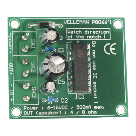
- Page 10 7. PCB layout.
- Page 11 Diagram 8. Diagram...
- Page 12 VELLEMAN Components NV Legen Heirweg 33 9890 Gavere Belgium Europe www.velleman.be www.velleman-kit.com Modifications and typographical errors reserved © Velleman Components nv. H8066IP - 2004 - ED1 5 4 1 0 3 2 9 3 2 5 3 4 3...
Need help?
Do you have a question about the K8066 and is the answer not in the manual?
Questions and answers