Advertisement
Total solder points: 29
Difficulty level: beginner 1
2
ILLUSTRATED ASSEMBLY MANUAL
3
4
5
advanced
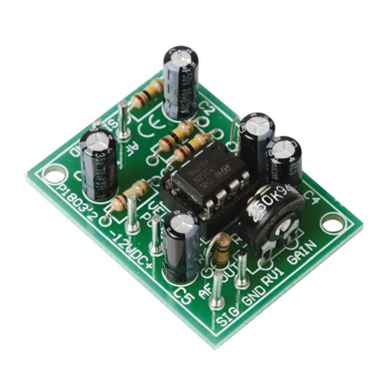
UNIVERSAL MONO PREAMPLIFIER
K1803
Specifications
Power supply: 10-30VDC / 10mA.
Output impedance: 1Kohm.
Adjustable output level: max. 40dB.
Frequency range: 20Hz to 20kHz ± 3dB.
Max. input signal: 40mV.
PCB dimensions: 30 x 40mm (1.2" x 1.57").
H1803IP'2
Advertisement
Table of Contents

Related Manuals for Velleman K1803


Summary of Contents for Velleman K1803
- Page 1 Total solder points: 29 Difficulty level: beginner 1 advanced UNIVERSAL MONO PREAMPLIFIER K1803 Specifications Power supply: 10-30VDC / 10mA. Output impedance: 1Kohm. Adjustable output level: max. 40dB. Frequency range: 20Hz to 20kHz ± 3dB. Max. input signal: 40mV. PCB dimensions: 30 x 40mm (1.2" x 1.57").
- Page 2 VELLEMAN NV Legen Heirweg 33 9890 Gavere Belgium Europe www.velleman.be www.velleman-kit.com...
- Page 3 Assembly hints 1. Assembly (Skipping this can lead to troubles ! ) Ok, so we have your attention. These hints will help you to make this project successful. Read them carefully. 1.1 Make sure you have the right tools: • A good quality soldering iron (25-40W) with a small tip.
- Page 4 REMOVE THEM FROM THE TAP E ONE AT A TIME ! DO NOT BLINDLY FOLLOW THE ORDER OF THE COMPONENTS ONTO THE TAPE. ALWAYS CHECK THEIR VALUE ON THE PARTS LIST! You will find the colour code for the resistances on our website: www.velleman.be...
- Page 5 Construction 1. Resistors 3. Vertical resistors 5. Electrolytic capacitors. Watch the polarity ! R... C1 : 10µF R... C... C2 : 10µF C3 : 10µF C4 : 10µF C5 : 10µF R1 : 100K (1 - 0 - 4 - B) R5 : 100K (1 - 0 - 4 - B) R2 : 100K (1 - 0 - 4 - B) R6 : 100K (1 - 0 - 4 - B)
- Page 6 Connection 8. Connection Connect a stabilized supply between 10 and 30V with the points “+” and “-” on the print. The input is connected on the points “AF IN”. The output is taken on the connection “AF OUT” and the ground “-”. To connect your in–...
- Page 7 Schematic diagram & PCB 9. Schematic diagram. 10. PCB 220K 100K IC1B IC1A 10µ 10µ 10µ 100K AF IN 10µ AF OU T 100K 100K 100K 10µ...
- Page 8 Modifications and typographical errors reserved VELLEMAN NV © Velleman nv. Legen Heirweg 33, 9890 Gavere H1803IP - 2010 - ed.2 Belgium - Europe 5 4 1 0 3 2 9 4 3 4 9 7 7...
Need help?
Do you have a question about the K1803 and is the answer not in the manual?
Questions and answers