
Related Manuals for Velleman K8040


Summary of Contents for Velleman K8040
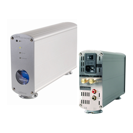
- Page 1 Total solder points: 299 Difficulty level: beginner 1o 2o 3o 4o 5þ advanced HIGH-END mono mosfet power amplifier K8040 8040 Mosfet Power Amplifier Temp. error Clip/Auto power ILLUSTRATED ASSEMBLY MANUAL H8040IP-1...
- Page 2 VELLEMAN COMPONENTS Legen Heirweg 33 9890 Gavere Belgium http://www.velleman.be...
- Page 3 Assembly hints 1. Assembly (Skipping this can lead to troubles ! ) Ok, so we have your attention. These hints will help you to make this project successful. Read them carefully. 1.1 Make sure you have the right tools: A good quality soldering iron (25-40W) with a small tip.
- Page 4 Assembly hints Use the check-boxes to mark your progress. Please read the included information on safety and customer service * Typographical inaccuracies excluded. Always look for possible last minute manual updates, indicated as ‘NOTE’ on a separate leaflet. 1.3 Soldering Hints : 1- Mount the component against the PCB sur- face and carefully solder the leads 2- Make sure the solder joints are cone-...
- Page 5 Color code table...
- Page 6 Construction CONSTRUCTION The unit consists of one main PCB with all the components including trans- former and power supply. Tip: The pictures on the packaging can be used as a guideline. However, due to possible modifications they are not 100% reliable. Mount the components in the order described: 3.
- Page 7 Construction q R9: 15K (1-5-3) 5. Multilayer capacitors q R10: 15K (1-5-3) q R11: 470R (4-7-1) c... q R12: 15K (1-5-3) q R13: 15K (1-5-3) q R14: 100R (1-0-1) q R15: 15K (1-5-3) q R16: 2K2 0.6W (2-2-2-9) q R17: 100R (1-0-1) q R18: 1K (1-0-2) q R19: 470R (4-7-1) q C1: 100n (104, 0.1, u1)
- Page 8 Construction 8. Capacitors 10. RCA connectors. Mount them straight and against the PCB q C9: 2n2 (222, 2200) q SK1: MJ-523AG/R q C10: 220n (.22, u22, 224) q SK2: MJ-523AG/B q C11: 1uF q C12: 1uF Tip: q C13: 2.2uF A red and a black type are delivered q C14: 2.2uF with the kit, if you bought two amplifi-...
- Page 9 Construction 12. Terminal blocks 13. Terminal connectors Check that the position corresponds with the PCB silk printing. q SK3: 3 pole Mains in q SK4: 3 pole Mains transformer q SK7: 2 pole Temp sensor q SK8: 2 pole Power meter SK...
- Page 10 Construction 14. Coil 16. Voltage regulator. The back side corresponds to the thick line. L... VR... This coil will have to be made by yourself. Use the supplied copper wire (1.5mm) with the kit. Wind this wire round a 8mm drill or other round object and make 8 turns.
- Page 11 Construction 18. Bridge rectifier. 20. Power electrolytic capacitors. Check the polarity !! Check the polarity ! C... q BR1: RS603 q C31: 10.000µF q C32: 10.000µF 19. LEDs q C33: 10.000µF q C34: 10.000µF COLOR= 2...5 21. Insert the IC’s into their sock- LD...
- Page 12 Construction 22. Mounting front LED’s. Check the polarity ! Short lead = Cathode or— ! CAUTION: After bending the leads the long LD... appearing lead will be the cath- ode! CATHODE First: Bend the leads exactly like the IMPORTANT drawing. Mount these LED’s exactly like in the drawing, otherwise some LED’s will Next: Solder one lead, and check the...
- Page 13 Construction 23. Mounting the Power IC q IC4: TDA7293 Mount the support plate onto the IC as shown in the drawing. Put a drop of silicone compound on both sides of the mica isolator. Also check the position of the plastic isolator A. ATTENTION : The bolt should be inserted on the side of the IC holder with the countersunk opening B ! Drop of heat conductive...
- Page 14 Construction 24. Mounting the power transformer and mains voltage selection Mount the transformer as in the drawing (see also the picture on the packaging) Use the supplied straps (4 pcs) to fix the transformer. Primary windings (MAINS) connection: Check the table on the PCB for the correct voltage selection and connect the wires : For 230V (220V to 240V), edge orange, then brown and black.
- Page 15 Enclosure preparation 25. Enclosure preparation q Cut the thread in the holes for the enclosure feet in one of the alumi- num profiles, us- ing the supplied FIG. 1 special M4 screw as a tap. q Mount the feet on the aluminum profile, using two M4 hexagonal Al- len screws.
- Page 16 Enclosure preparation q Position the main PCB in the aluminum profile that is prepared with the feet. q Mark the center position of the three fixation holes on the aluminum. A refer- ence indication is also on the PCB edge. FIG.
- Page 17 Enclosure preparation q Using an ohmmeter, measure between the edge of the aluminum profile and the back spacer, if there is a good electric contact (less then 10 ohm). If not, repeat the above step to remove the paint under the spacer. FIG.
- Page 18 Final assembly 26. final PCB mount RE-CHECK CAREFULLY THE PCB FOR MOUNTING AND SOLDERING ERRORS! q Mount the pcb into the enclosure, check the position of the power IC. The IC support must fit onto the previously inserted hexagonal bolts. Make sure there is silicone compound between the IC support and the enclosure! Glue the included insert C between the transformer and housing.
- Page 19 Final assembly 27. Speaker and mains connector assembly Prepare the wiring of the mains connector like in the drawing. First mount the switch into the mains connector assembly. Do not forget to isolate the soldering connections using a piece of shrink tube. Use the supplied 0.5mm wire: Blue for Neutral Brown for Live...
- Page 20 Final assembly 28. Final assembly and connection q Solder a 15cm (2.5mm) wire to the LS connectors. Black = negative, Red= positive, use a shrink tube to isolate the connection.. q Solder a spade terminal to the other end, do not forget the terminal isolation. 15cm q Mount (insert) the mains connector onto the rear panel.
- Page 21 Final assembly q Mount the rear panel onto the enclosure, using two M4 Allen screws. q Connect the speaker wires to the speaker output tabs. Check the polatity! Black= LS-, Red= LS+. DO NOT CONNECT THE MAINS WIRING WITH THE PCB YET!
- Page 22 Final assembly 29. Preparing the front panel q Connect the two wired connector to the meter, RED = +, BROWN = - to the meter. q Mount the power meter onto the front panel. q Fix the meter using a piece of transparent ad- hesive tape (four sides).
- Page 23 Test 30. Test 21. Mains voltage connection Check again all connections of transformer and mains preparation q Connect the mains wires to the mains connector SK3, Blue= Neutral, green/ yellow= Earth. q Connect a 60W light bulb in series with the Live (Brown wire) and the Live q Connect a 10cm blue wire to the connection on the PCB.
- Page 24 Test Test continued: Now push the DC protection test button SW2, the bulb should light if the but- ton is pressed. Be careful not to touch any exposed live parts. Disconnect the mains plug. Now the brown Live wire can be connected directly to the connector AK3. Check the user manual to test all functions and operation of the unit.
- Page 25 DIAGRAMS...
- Page 26 470K 470K L53MWC backlight L-424YDT LED3RL LED3RL STBY-GND BUFFER DRIVER -PWVs +PWVs...
- Page 28 VELLEMAN Components Legen Heirweg 33 9890 Gavere Belgium Europe Info ?: http://www.velleman.be Modifications and typographical errors reserved © Velleman H8040IP - 2001 - ED1...
Need help?
Do you have a question about the K8040 and is the answer not in the manual?
Questions and answers