Advertisement
Quick Links
Total solder points: 600
Difficulty level:
beginner 1o 2o 3o 4o 5þ advanced
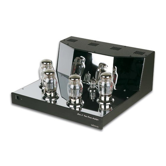
MONO
PURE
CLASS
A
VALVE
POWER AMPLIFIER
K8010
⇒ Pure CLASS A valve sound with high quality KT88 valves
⇒ High quality chrome plated enclosure
⇒ Chrome plated valve socket covers
⇒ Easy bias adjustment with LED indication
⇒ Removable bottom for easy access and service
⇒ High quality capacitors and components
⇒ Gold plated input and speaker terminals
⇒ Standby function
⇒ Soft start circuit for power transformer
⇒ Sensitivity adjustment for exact matching of two mono amps
Specifications
• Full class A 65Wrms in 4 or 8Ω
• Bandwidth: 4Hz to 90KHz (-3dB/1W)
• Harmonic distortion: 0.1% @ 1W/1KHz
• Signal to noise ratio: >110dB (A weighted)
• Input sensitivity: 1Vrms (adjustable)
• Power supply: 100, 120, 230 or 245VAC
• Power consumption: 230VA max.
• Dimensions: 355W x 360D x 157H
• Weight: 14Kg / 31lb
modifications reserved
MANUAL
H8010P-ED1
Advertisement

Related Manuals for Velleman K8010


Summary of Contents for Velleman K8010
- Page 1 MONO PURE CLASS VALVE POWER AMPLIFIER K8010 ⇒ Pure CLASS A valve sound with high quality KT88 valves ⇒ High quality chrome plated enclosure ⇒ Chrome plated valve socket covers ⇒ Easy bias adjustment with LED indication ⇒ Removable bottom for easy access and service ⇒...
- Page 2 COLOR= 2… 5 4K7= ( 4 - 7 - 2 - B ) 4K7= ( 4 - 7 - 0 - 1 - 1 ) COLOUR CODIFI- KLEUR CODICE CODIGO CODIGO VÄRI FÄRG FARVE FARGE FARB CODE CATION KODE SCHEMA DE COL- COLORE KOODI...
- Page 3 __________________________________________________________________________________________________________________________________________________________ TECHNICAL DATA* • Output power: 65 Wrms class A / 85Wrms maximum • Output impedance 4 or 8 Ohm • Ultra linear output transformer • Switch-on delay, to protect the output tubes: approx. 1 minute • Standby circuit • Built-in bias current indicator •...
- Page 4 _______________________________________________________________________________________________________________________________________________________ 1. Assembly (Skipping this can lead to troubles ! ) Ok, so we have your attention. These hints will help you to make this project successful. Read them carefully. 1.1 Make sure you have the right tools: • A good quality soldering iron (25-40W) with a small tip. •...
- Page 5 __________________________________________________________________________________________________________________________________________________________ ASSEMBLY OF THE MAIN PCB P8010 Foreword: For best results and easy handling of the large PCB (Printed Circuit Board), we will start by putting the four large valve sockets in place. This will allow us to rest the board on the bench, without having the component leads touching the bench surface.
- Page 6 _______________________________________________________________________________________________________________________________________________________ 1. VALVE SOCKET MOUNTING Check the position of the notch in the centre of the valve socket, it must correspond to the position of the notch in the circle printed on the PCB. Connect the leads to the corresponding isles on the PCB using a small piece of supplied jumper wire.
- Page 7 __________________________________________________________________________________________________________________________________________________________ 2. JUMPERS 3. JUMPERS FOR AC POWER SE- LECTION Note that for J1 to J4, two jumper wires have to be mounted in the same hole, for extra cur- For 100V input (mains), mount: rent handling. JA at the voltage selection 1 In order to get nice straight wiring, without too much folding and measuring, follow these hints:...
- Page 8 _______________________________________________________________________________________________________________________________________________________ 4. DIODES (Check the polarity!) For 220V - 230V input, mount: JC at the voltage selection 1 D... CATHODE D1: 1N4148 JC at the voltage selection 2 D2 :1N4148 D3: 1N4007 D4: 1N4148 D5: 1N4007 D6: 1N4148 For 240V -245V mains input, mount: D7: 1N4148 JD at the voltage selection 1 D8: 1N4148...
- Page 9 __________________________________________________________________________________________________________________________________________________________ R21: 10K (1 - 0 - 3 - B) 5. ZENER DIODES R22: 1K5 (1 - 5 - 2 - B) (Check the polarity!) R23: 1K2 (1 - 2 - 2 - B) R24: 560 (5 - 6 - 1 - B) R25: 100K (1 - 0 - 4 - B) R26: 220K (2 - 2 - 4 - B) ZD...
- Page 10 _______________________________________________________________________________________________________________________________________________________ 7. 1W RESISTORS 8. LEDs (Check the polarity!) R... COLOR = 2...5 LD... CATHODE LD1: 5mm RED (2) BLINKING R55: 270 (2 - 7 - 1 - B) LD2: WILL BE MOUNTED R56: 10K (1 - 0 - 3 - B) LATER, SEE SECTION 27 R57: 10K (1 - 0 - 3 - B) LD3: 3mm YEL (4)
-
Page 11: Dip Switches
__________________________________________________________________________________________________________________________________________________________ 10. REED RELAYS 12. RESISTOR TRIMMERS (Check the position of the notch!) Vertical type PIN 1 RV... RY... RY1: VR05R121 RV1: 100K RV2: 100K 11. DIP SWITCHES RV3: 100K RV4: 100K Horizontal type SW... RV... Check that switch 1 corresponds to pin 1. SW2: DS-4P RV5: 500K (470K) - Page 12 _______________________________________________________________________________________________________________________________________________________ 13. TRANSISTORS 15. PCB BLADE TERMINALS Mount them as straight AS possible against the PCB. A good solder joint is very important ! T... T... SK... T... T... SK1: 4 Ohm SK2: GND SK3: 8 Ohm T1: BC516 SK4: BLUE T2: BC547C SK5: RED T3: BC547C...
- Page 13 __________________________________________________________________________________________________________________________________________________________ 17. PCB TERMINAL BLOCK 19. SWITCH some blocks slide into each other ! SW... IMPORTANT: Don't leave a gap between Mount these terminals with the wire inputs fac- the SWITCH and the PCB! ing the PCB edge: SK12: 2 POLE (large) SK13: 3 POLE SK14: 3 POLE SK15: 3 POLE...
-
Page 14: Electrolytic Capacitor
_______________________________________________________________________________________________________________________________________________________ 21. POWER RELAYS 22. ELECTROLYTIC CAPACITOR The various relays have footprints that corre- (Check the polarity!) spond to the footprints on the PCB: RY2: VR10V121C RY3: VR10V121C C... RY... C14: 4µ7 C15: 100µF RY4: VR5V122C C16: 470µF C17: 470µF C18: 470µF C19: 470µF C20: 47µF/100V... - Page 15 __________________________________________________________________________________________________________________________________________________________ 23. TRANSFORMER 25. INSERT THE IC (Check the position of the notch!) PIN 1 IC... TRAFO... IC1: LM3914 TRAFO1: 12VAC 24. ELECTROLYTIC CAPACITOR (Check the polarity!) Generally these capacitors are of the snap-in type and cannot be mounted incorrectly. C...
-
Page 16: Valve Wiring
_______________________________________________________________________________________________________________________________________________________ 26. 6.3V VALVE WIRING Wiring for the 4 valve sockets V1 to V4. Use the supplied brown wire. Twist them as shown in the illustration. The polarity is not important. For safety, it is advisable to check with an ohmmeter that the two 6.3V terminals are not shorted when the wiring is completed. - Page 17 __________________________________________________________________________________________________________________________________________________________ ASSEMBLY INTO THE CABINET: • Mount the caged nuts into the square holes as shown in the illustration. These nuts are later used to fasten the covers. CLICK INTO HOLE FIG 1 • Mount the chromed feet on the four cabinet corners, with an M4 bolt. To avoid scratches on other equipment, you can stick a piece of felt on every foot (not supplied).
- Page 18 _______________________________________________________________________________________________________________________________________________________ M3 BOLT MAINS INLET M3 LOCK WASHER M3 NUT FIG 3...
- Page 19 __________________________________________________________________________________________________________________________________________________________ • Make the connections as shown. Use the supplied blue wire for the neutral (N) terminal, and brown wire for the live (L) terminal. FIG 4 The earth terminal is hooked up with green/yellow striped wire. The female push-on connector on the green/yellow striped wire must be soldered for best results.
- Page 20 _______________________________________________________________________________________________________________________________________________________ • Use the supplied 1,5mm² wire to make the connections. For best results, solder the female push-on connector (fig 5). Apply enough heat, in order to make a good solder joint. FIG 7 • Mounting of the toroid transformers : The output transformer marked ZD043 must be fitted according to the illustration, on the right hand side of the cabinet.
- Page 21 __________________________________________________________________________________________________________________________________________________________ • Connect the double yellow wire with the connector marked ‘YELLOW’ SK6. Connect the red wire with the connector marked ‘RED’ SK5. Connect the blue wire with the connector marked ‘BLUE’ SK4. Use the supplied female push-on connectors (fig 5) and solder them onto the wires ! Connect the remaining wires to the terminal blocks SK16 and SK17.
-
Page 22: Final Inspection
_______________________________________________________________________________________________________________________________________________________ • Connect the grey wires to the connectors marked SK7 and SK8 (GRAY). Connect the green wires to the connectors marked SK9 and SK10 (GREEN). Connect the remaining leads to the terminal blocks SK13, SK14 and SK15 FINAL INSPECTION : WARNING : THE PCB CARRIES VOLTAGES THAT EXCEED 400V ! THESE VOLTAGES CAN KILL ! MAKE SURE NO ONE CAN TOUCH ANY LIVE PARTS Use suitable isolated measuring equipment... - Page 23 __________________________________________________________________________________________________________________________________________________________ FIG 12 SWITCH OFF THE UNIT AND REMOVE THE MAINS PLUG. WAIT A COUPLE OF MINUTES UNTIL THE DANGEROUS HIGH VOLTAGE HAS DISSAPEARED (UNTIL HIGH VOLTAGE INDICATOR LD13 TURNS OFF) • Put the small valves in place: V6 type ECC82 or 12AU7, CV491, 6189, 8136 V5 type ECC81 or 12AT7, CV455, 6201, 8162 •...
- Page 24 _______________________________________________________________________________________________________________________________________________________ Put the first switch in the ON position (use a pen or a small screwdriver) Gently turn RV1 clockwise until the second or third LED lights (LD4 or LD5) Switch off the first switch. Switch on the second switch Gently turn RV2 clockwise until the second or third LED lights (LD4 or LD5) Perform the same operation with RV3 and RV4 Wait for about 10 minutes, before continuing the rest of the calibration.
-
Page 25: Troubleshooting
__________________________________________________________________________________________________________________________________________________________ length of yellow/green striped wire and 2 female push-on terminals. Make sure you solder both ter- minals. (See fig 5) • Mount the top cover on the enclosure (Make sure the earth lead of the vertical plate is bent down, so it does not get squeezed between the lid and the enclosure). - Page 26 If you have the impression that for some reason, the unit still does not operate as it should, you can send it to our technical dept. for inspection. Send the PCB only, not the enclosure or the transformers. Use the original box. Include a detailed description of the fault. Check www.velleman-kit.com for your nearest Velleman dealer.
- Page 27 __________________________________________________________________________________________________________________________________________________________ DIAGRAMS...
- Page 28 FROM OUTPUT TRANSFORMER 100VDC 190VDC 75VDC K8010: 3.6VDC K8011: 0.4VDC K8010: 3.6VDC K8011: 0.4VDC TO POWER ON SWITCH SK18 VELLEMAN P8010'1 / P8011'1 DANGER HIGH VOLTAGE K8010: 3.6VDC K8010: 3.6VDC K8011: 0.4VDC K8011: 0.4VDC SK19 TO POWER ON LED SK20...
- Page 29 __________________________________________________________________________________________________________________________________________________________ DIAGRAM POWER SUPPLY SECTION...
- Page 30 _______________________________________________________________________________________________________________________________________________________ DIAGRAM AMPLIFIER SECTION...
Need help?
Do you have a question about the K8010 and is the answer not in the manual?
Questions and answers