
Related Manuals for Velleman K8021


Summary of Contents for Velleman K8021
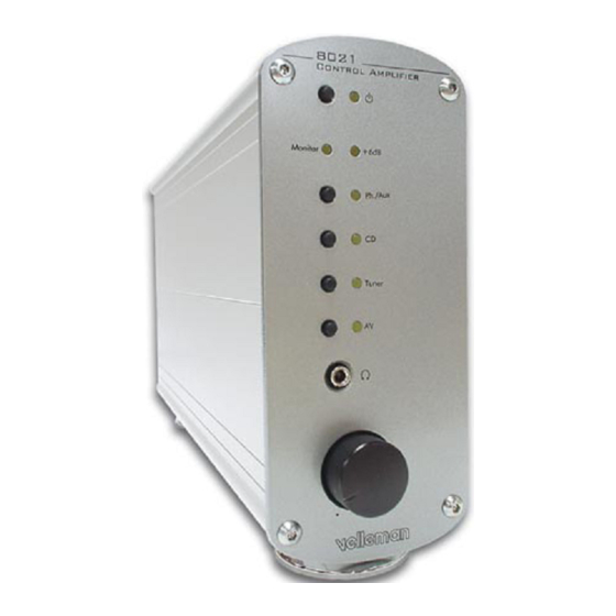
- Page 1 Total solder points: 500 Difficulty level: beginner 1o 2o 3o 4o 5þ advanced HIGH-END CONTROL AMPLIFIER K8021 ILLUSTRATED ASSEMBLY MANUAL H8021IP-1...
- Page 2 VELLEMAN KIT NV Legen Heirweg 33 9890 Gavere Belgium http://www.velleman.be...
- Page 3 Assembly hints 1. Assembly (Skipping this can lead to troubles ! ) Ok, so we have your attention. These hints will help you to make this project successful. Read them carefully. 1.1 Make sure you have the right tools: • A good quality soldering iron (25-40W) with a small tip.
- Page 4 Assembly hints ⇒ Use the check-boxes to mark your progress. ⇒ Please read the included information on safety and customer service * Typographical inaccuracies excluded. Always look for possible last minute manual updates, indicated as ‘NOTE’ on a separate leaflet. 1.3 Soldering Hints : 1- Mount the component against the PCB sur- face and carefully solder the leads...
- Page 5 Color code table...
- Page 6 Construction CONSTRUCTION The unit consists out of two PCB’s, one is the main PCB, P8021B and the other is the left channel input section P8021L. First we will start with the small P8021L, then we assemble the P8021B. Tip: The pictures on the packaging can be used as a guideline.
- Page 7 Construction 3. Capacitors 6. RCA connectors. Mount them straight and against the PCB C... q C1: 220p (221) q C2: 220p (221) q C3: 220p (221) q SK1: MJ-523AG/B BLACK q C4: 220p (221) q SK2: MJ-523AG/B BLACK q C5: 220p (221) q SK3: MJ-523AG/B BLACK q C6: 220p (221) q SK4: MJ-523AG/B BLACK...
- Page 8 Construction P8021B Assembly...
- Page 9 Construction 1. Jump wires 3. Zener diode (check the polarity) ZD... CATHODE q ZD1: 20V / 0.6W q J1... J25 4. Resistors (check the color code) 2. Diodes (check the polarity) D... R... CATHODE q R1: 10K (1-0-3) q R2: 10K (1-0-3) q D1: 1N4148 q R3: 10K (1-0-3) q D2: 1N4148...
- Page 10 Construction q R22: 1K (1-0-2) 5. Choke q R23: 560R/1% (5-6-0-0) q R24: 1K8/1% (1-8-0-1) q R25A or R25B: 1K5 (1-5-0-1) (*) L... q R26: 1K5 (1-5-2) L... q R27: 560R/1% (5-6-0-0) q R28A or R28B: 1K5 (1-5-2) (*) q L1: 1uH (1-0) * The position of R25 and R28 de- q L2: 1uH (1-0) pends on the supplied IC for IC2...
- Page 11 Construction 8. Capacitors 9. Reed relays (check the position of the notch) C... RY... q RY1: VR05051AS or eq. q C1: 220p (221) q RY2: VR05051AS or eq q C2: 220p (221) q RY3: VR05051AS or eq q C3: 220p (221) q RY4: VR05051AS or eq q C4: 220p (221) q RY5: VR05051AS or eq...
- Page 12 Construction 11. transistors 13. Push button Mount them straight against the PCB surface ! q SW1: TS-04PV q SW2: TS-04PV q T1: BC557 q SW3: TS-04PV q T2: BC557 q SW4: TS-04PV q T3: BC557 q SW5: TS-04PV q T4: BC557 q T5: BC557 q T6: BC557 Remark: The metal part of these but-...
- Page 13 Construction 15. RCA connectors. 17. Voltage regulator. Mount them straight and The back side corresponds to against the PCB the thick line. VR... q SK1: MJ-523AG/R RED q SK2: MJ-523AG/R RED q SK3: MJ-523AG/R RED q SK4: MJ-523AG/R RED q SK5: MJ-523AG/R RED q VR1 UA7815 q VR2 UA7915 q SK6: MJ-523AG/R RED...
- Page 14 Construction 19. Volume potentiometer. 20. Mains voltage selection Use a piece of isolated brown wire to select the mains (outlet) voltage, as RV... indicated on the PC board. q For 115Vac (100 to 120Vac) A jumper between A-B, and a jumper q RV3: STRK27103 (2x50K ALPS) between C-D.
- Page 15 Construction 22. Mounting the LED’s. Check the polarity ! Short lead = Cathode or— ! CAUTION: After bending the LD... leads the long appearing lead will be the cath- ode! CATHODE First: Bend the leads exactly like the drawing. IMPORTANT Mount these LED’s exactly like in the Next: Solder one lead, and check the drawing, otherwise some LED’s will...
- Page 16 Construction 23. Mounting the sub PCB support q Mount four 2cm (0.8”) M3 spacers at the indi- cated positions using four 6mm (0.23”) M3 screws.
- Page 17 Enclosure preparation 24. Enclosure preparation q Cut the thread in the holes for the enclosure feet in one of the alumi- num profiles, us- ing the supplied FIG. 1 special M4 screw as a tap. q Mount the Feet on the aluminum profile, using two M4 hexagonal Al- len screws.
- Page 18 Enclosure preparation q Position the main PCB in the aluminum profile that is pre- pared with the feet. The potenti- ometer must be at the same side of the feet. FIG. 5 Align pcb with profile ! q Mark the center position of the three fixation holes on the aluminum.
- Page 19 Enclosure preparation q Remove the pcb and use a knife or a screwdriver to scratch the paint from the aluminum fixation, from the hole closest to the back end. This fixation will be used later to connect the ground and earth. FIG.
- Page 20 Final assembly 25. Potentiometer assembly and final PCB mount q Mount the PCB into the enclosure like before. Tip: Check if the pcb does not have to much play at the potentiometer posi- Play? tion. If there is too much play, put a piece of tape round the edge of the pcb to remove the slack.
- Page 21 Final assembly q Now carefully mount the front panel, using two M4 Allen screws. Check the position of the LED’s. q Check if the potentiometer turns smoothly without touching the front panel, otherwise correct his position or the position of the front panel. q Check if the phones connector (metal part) does not touch the front panel.
- Page 22 Final assembly 26. Final assembly and connection q Mount (insert) the mains connector onto the rear panel. Insert a 250mA fuse into the connector (there is also room for a spare fuse). q Mount the rear panel onto the enclosure, using two M4 Allen FIG.
- Page 23 Test and adjustment 27. Test and adjustment Connect the mains AC voltage to the mains connector. Check if the power LED (in the center of the PCB) is lit. This means that the +15V and –15V are correct. CAUTION: Some points on the PCB are connected to the dangerous mains voltage.
- Page 24 RV3B 2.2uF 100n 1N4148 Monitor R28B TLE2071 / OPA134 / OPA604 100K LINE OUT R 330R BC557 560R/1% 220p BC557 1K/1% 1K8/1% -15VR 100n Mute +6dB 1N4148 SK13 220p 220p RIGHT INPUT / OUTPUT SECTION © Velleman Kit AMPLIFIER SECTION...
-
Page 25: Power Supply Section
1N4007 MAINS 230V 115V 100n 470µ 100n 100n 100µ SK14 FASTON POWER SUPPLY SECTION To Cover 100n 220p OSC1/CLKIN OSC2/CLKOUT T0CKI MCLR/VPP TUNER Input1 Input2 Input3 PIC16C54RC Input4 PU/LINE +6dB Mute Monitor STBY / MUTE CONTROLLER SECTION © Velleman Kit... - Page 26 Diagram PU/LINE BC557 220p 1N4148 BC557 220p 1N4148 TUNER BC557 220p 1N4148 BC557 220p 1N4148 MONITOR BC557 220p 1N4148 LINE OUT L 330R 220p BC557 1N4148 LEFT INPUT SECTION © Velleman Kit...
- Page 27 Notes NOTES:...
- Page 28 VELLEMAN KIT NV Legen Heirweg 33 9890 Gavere Belgium Europe Info ?: http://www.velleman.be Questions ?: support@velleman.be Modifications and typographical errors reserved © Velleman Kit nv H8021IP - 2000 - ED1...
Need help?
Do you have a question about the K8021 and is the answer not in the manual?
Questions and answers