
Subscribe to Our Youtube Channel
Related Manuals for Shini SICC-A-R2 Series


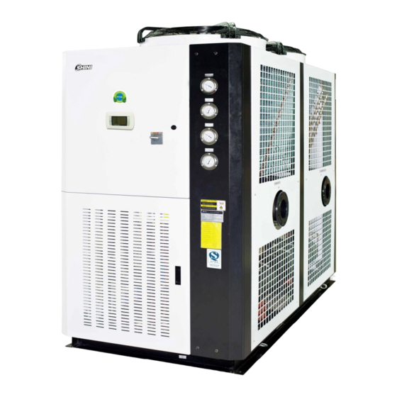
Summary of Contents for Shini SICC-A-R2 Series
- Page 1 SICC-A-R2 CFC-free Refrigerant Air-cooled Central Water Chiller Date:Nov, 2017 Version: Ver.B (English)
-
Page 3: Table Of Contents
General Description ..................7 1.1 Coding Principle ..................8 1.2 Feature ....................8 1.3 Technical Specifications ................ 10 1.3.1 SICC-A-R2 Series Outline Dimensions ........10 1.3.2 Flange ..................11 1.3.3 Technical Specification ............... 12 1.4 Safety Regulations ................13 1.4.1 Notice for Safe Operation ............13 1.4.2 Safety Signs and Labels ............. - Page 4 4.2 Interface Operation ................28 4.2.1 Initial Interface ................28 4.2.2 Main Interface ................29 4.2.3 Interface of “on” and “off” ............29 4.2.4 Current Fault Checking and Resetting ........31 4.2.5 Password Input and Change ............32 4.3 Instruction of Menu Interface ..............33 4.3.1 Menu Instruction of “A Setting”...
- Page 5 Table 3-1: Notice for Lifting Matters ..............20 Table 4-1: Instruction of Keys ................28 Picture Index Picture 1-1: Outline Dimensions ............... 11 Picture 1-2: Flange Outline Dimensions ............11 Picture 2-1: Working Principle ................16 Picture 3-1: Installation Space ................18 Picture 3-2: Platform Installation ...............
- Page 6 6(44)
-
Page 7: General Description
Read this manual carefully before operation to prevent damage of the machine or personal injuries. SICC-A-R2 series is applicable for cooling moulds to reduce product’s molding cycle. They can also be used for equipment cooling in order to maintain a normal temperature as well as other industrial cooling. -
Page 8: Coding Principle
1.1 Coding Principle 1.2 Feature Standard configuration l Modularized design makes it easier to combine module units 1 to 15. Cooling capacity can be enlarged by increasing the number of modules or choose appropriate modules to connect to existing system. l The water route of the modules can be linked by one module connecting to the inlet/outlet water tube. - Page 9 Chapter 6, which contains service instructions intended for service engineers. Other chapters contain instructions for the daily operator. Any modifications of the machine must be approved by SHINI in order to avoid personal injury and damage to machine. We shall not be liable for any damage caused by unauthorized change of the machine.
-
Page 10: Technical Specifications
1.3 Technical Specifications 1.3.1 SICC-A-R2 Series Outline Dimensions (SICC-60A-R2) (SICC-90A-R2) 10(44) -
Page 11: Flange
(SICC-120A-R2) Picture 1-1: Outline Dimensions 1.3.2 Flange Picture 1-2: Flange Outline Dimensions 11(44) -
Page 12: Technical Specification
1.3.3 Technical Specification Table 1-1: Technical Specification Model SICC-60A-R2 SICC-90A-R2 SICC-120A-R2 Item Refrigeration Capacity Kcal/hr 51,600 77,400 103,200 Power 3Ф 400VAC 50Hz Total Power Running Current Startup Current Type Scroll Power 8.6×2 12.5×2 17× 2 Compressure Crank Case Heater 0.08×2 0.08×2 0.056×2 Type... -
Page 13: Safety Regulations
1.4 Safety Regulations Strictly abide by the following safety regulations to prevent damage of the machine or personal injuries. 1.4.1 Notice for Safe Operation Read the following regulations before installation or using under the consideration of safety. 1) Do not drop water in the electrical part to avoid insulation damage. 2) Put device connect to ground according to electrician operating regulation to avoid creepage. -
Page 14: Safety Signs And Labels
1.4.2 Safety Signs and Labels Attention! The installation of electrical devices should be conducted by professional electricians. During repairing and maintenance, must turn off the main switch and control switch. Warning! High Voltage danger! Put up this symbol in the shell of the electric cabinet. Warning! Be careful! This symbol should take more careful hereby! -
Page 15: Exemption Clause
Shini (including employees and agents). Shini is exempted from liability for any costs, fees, claims and losses caused by reasons below: 1. Any careless or man-made installations, operation and maintenances upon machines without referring to the Manual prior to machine using. -
Page 16: Structure Characteristics And Working Principle
Structure Characteristics and Working Principle 2.1 Working Principle Picture 2-1: Working Principle 2.1.1 Working Flow Instruction Cooling circulation: the high temp. high pressure air from compressor’s high pressure spraying outlet comes into fin-type-air side heat exchanger, which works as a condenser to cool down the air into liquid. Then it comes into expansion valve after filtration. -
Page 17: Installation And Debugging
Installation and Debugging Note : Before installation, please read this chapter carefully and install according to the procedures as follows! Install the water chiller near windows or places with good air flowing because air-cooled central water chiller needs a good heat-releasing condition. If the water chiller is installed inside the factory, then the surrounding temperature should not be higher than 35 ℃... -
Page 18: Select Installation Site
Note: Power connection must be conducted by professional electricians! Do not change the circuit of the water chiller without our company's authority. If the machine is damaged by unauthorized change we are not responsible for this. 3.2 Select Installation Site 1) No heat source existence nearby to acoid efficiency reduction due to absorbing hot air. -
Page 19: Bearing Platform
3.3 Bearing Platform 1) The unit should be installed on concrete or steel structure bearing platform that is firm and the surface of the baring platform should be smooth and flat. The in tensity of the platform should hold the whole unit, if the intensity is not strong enough, it is easy to cause vibration and noise. -
Page 20: Hanging And Transporting Of The Unit
3.4 Hanging and Transporting of the Unit 1) Propose plans of hanging and transporting before practise, including entering date for each unit, dimensions of appearance, weight, path, reserved holes, hanging and transporting device as well. Figure 3-1 shows the details. Table 3-1: Notice for Lifting Matters Items Check points... -
Page 21: Water System Tubing
3.5 Water System Tubing 1) The inlet /outlet pipes and valves of the unit should have itselves insulated. The outside parts should have protective veil to prevent the thermo lost and dewfall happen and this brings no impact on building structure and anti-freezing when it is in winter. - Page 22 Names of Parts: 1. Stop valve 2. One way valve 3. Y type filtration valve 4. Pump 5. Pressure gauge 6. Thermometer 7. Flowmeter 8. Solenoid valve 9. Rubber soft pipe Picture 3-4: Same Direction Way 1 Names of Parts: 1.
-
Page 23: Combined Installation Of Modules
3.6 Combined Installation of Modules 1) Disassembly the sideplates around the machine, calibrate the cooling water inlet to combine the modules. Use rubber soft pipe to connect the module's chilling water pipe. 2) The non-exist end of the cooling water pipe should be fixed by flange. 3) Refers to wiring diagram to tandem the communication line to next submodule, the communication line of which tandems to next submodule thereby. - Page 24 can not be shorter. Then enlarge the diameter of the cable. 6) The wiring connection between power and unit should be conducted according to electrical regulations with good insulation, after the unit being connected to the power; the terminals of the electrical components resistance should be at least more than 3MΩ.
-
Page 25: Communication Connection
3.8 Communication Connection This series machine adopts modular structure, and signals between modules are communicated based on CPP bus. So the controller of each module should have the only address. Note: Please refer to Chapter 4 for the function of each press key on the displayer. -
Page 26: Displayer Reset
5) When the displayer shows Self test and please wait, continuously press the <alarm key> and <Up key> till the screen displays plan address, and use the <Up key> or <Down key> to modify the address to 2 or other value (it is set according to actual demand on site. - Page 27 Picture 3-8: Communication Line Connection 2) Communication Interface Picture 3-9: Communication Interface Diagram Note: The communication cable plug-in and plug-out must be carried when controller powered off. Otherwise, communication interface would be damaged easily. Note: The communication cable must be connected according to the specification.
-
Page 28: Operation Guide
Operation Guide 4.1 Introduction of Operation Menu Picture 4-1: Operation Menu Table 4-1: Instruction of Keys Keys Function Display the alarm list of operations or manual resetting of faults -Alarm Enter the main menu tree Return to the last screen Turn the list up or increase the value on the displayer Turn the list down or decrease the value on the displayer -Down... -
Page 29: Main Interface
4.2.2 Main Interface 4) The unit has been activated by keyboard. Display the inlet/outlet water temp 5) The main machine unit has of the system. been activated (this function Display the “on” and “off” state of only works in the the unit. - Page 30 activated, the key of can be subordinate machines will be pressed to turn on the machine. forced to start. And when the At that time, the keyboard of the main machine is in “off” state, unit is in “on” state. all subordinate machines will be turned off.
-
Page 31: Current Fault Checking And Resetting
zones, which expand from F1 to F4. Thus, on Monday, the unit is “on” in The interface setting is illustrated the periods of 8:00-12:00 and in detail in the menu interface 14:00-17:00, and is “off” in the rest instruction [B04] and [B05]. of time. -
Page 32: Password Input And Change
Display the cause of fault password is correct, the interface would automatically skip to the next one; if the password is not the right one, you would be prompted to input the password again. Password error: When the external alarm signal of current fault becomes free, the key under the “interface of fault checking”... -
Page 33: Instruction Of Menu Interface
4.3 Instruction of Menu Interface Press “Prg” in any interface of function tree to enter the main menu. Main Menu Catalogue Setting Clock Input and Output Alarm Record Switch Unit Maintenance Plant In the main menu, press the keys of to select a submenu of the first stage with cursor, and then press to enter this submenu, in which... -
Page 34: Menu Instruction Of "B Clock
temp is only displayed when water outlet is controlled. Alter the control range, i.e. control Control return difference ℃ the deviation value of target temp Only when water outlet temp is in loading zone and water inlet temp Water inlet resetting is higher than the reset temp can ℃... -
Page 35: Menu Instruction Of "C Input And Output
new password, so the clock password can be changed. 4.3.3 Menu Instruction of “C input and output” In the “main menu”, select “C input and output” with the cursor, and then press to enter the submenu of “input and output”, where keys of can be pressed to page up and down and to look up the input and output state of the current unit. -
Page 36: Menu Instruction Of "F Maintenance
Display the Internet connection state of State of units 9-16 module units 9-16. “Yes” means Internet is available. 4.3.6 Menu Instruction of “F Maintenance” In the “main menu”, select “F Maintenance” with cursor and then press enter the submenu of “maintenance”, where there is a submenu of the second stage. - Page 37 1) Switch between refrigeration and heating: remote control is activated, and the model is chosen through the input signal of digital value. 2) Keyboard switch: choose either refrigeration or heating by the menu maintenance parameter, which is presented in the interface [FC01] in detail. No matter which model is chosen, it takes effect only in the state of shutdown.
-
Page 38: Trouble-Shooting
Trouble-shooting Failures Possible reasons Solutions 1. NO power 1. Wait for power recovery Fan, pump and 2. Power switch jumps 2. Check the power and make it normal compressor can not 3. Power fuse is burnt. 3. Change power fuse start up 4. -
Page 39: Maintenance And Repair
Maintenance and Repair Note! All repairing work must be conducted by professional person to avoid personal injury and damage of machine. Matters require attention when do machine maintenance are as follows: 1) Do not stop the machine via cut the power supply unless emergncyoccurs. 2) When failure occurs and machine stops, press the main power switch (alarm light will go out). -
Page 40: Daily Repair And Check Items
5) Keep the unit dry, clean and ventilative. 6) The daily operation, unit management, maintenance and repair must be conducted by professional technicians. (Danger exists when dissembling and checking the unit, please take care!) 6.1 Daily Repair and Check Items 1) Operation, startup, stop, maintenance and repair works must be conducted by professional technicians to expand the unit's lifespan. -
Page 41: Maintenance Schedule
6.4 Maintenance Schedule 6.4.1 About the Machine Model Manufacture date Voltage Ф Frequency Power 6.4.2 Installation & Inspection Check if the pipe are connected correctly Check if the pipe has any leakage Check if the sealed joint has any crack Electrical component installation Voltage: Fuse melting current: 1 Phase... -
Page 42: Check Half-Yearly
6.4.7 Check Half-yearly Check and clean filter and expansion valve. Check the whole machine condition. Clean condenser. 6.4.8 Yearly Checking Check whether the contactor is normal. 6.4.9 3 year Checking PC board replacement. No fuse breaker replacement. 42(44) -
Page 43: Attachment:electrical Diagram
Attachment:Electrical Diagram 43(44) - Page 44 44(44)
Need help?
Do you have a question about the SICC-A-R2 Series and is the answer not in the manual?
Questions and answers