
Subscribe to Our Youtube Channel
Related Manuals for Shini SICC-A Series


Summary of Contents for Shini SICC-A Series
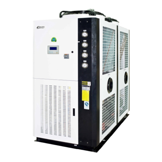
- Page 1 SICC-A Series Air-cooled Central Water Chiller Date: Apr, 2013 Version: Ver.B (English)
-
Page 3: Table Of Contents
General Description .................. 9 1.1 Coding Principle ................. 10 1.2 Feature....................10 1.3 Technical Specifications..............12 1.3.1 SICC-A Series Outline Dimensions ......... 12 1.3.2 The Illustrative Drawing of SICC-A Modules Grouping .... 15 1.3.3 Specification ................19 1.4 Safety Regulations ................20 1.4.1 Notice Items for Safe Operation .......... - Page 4 3.3 Bearing Platform ................39 3.4 Hanging and Transporting of the Unit ..........40 3.5 Water System Tubing................. 41 3.6 Combined Installation of Modules ............43 3.7 Essentials for Electric Wiring.............. 43 3.8 Power Connection................44 Operation Guide ..................45 4.1 Control Panel ..................
- Page 5 4.10.2 Interface Operation ..............50 4.11 Unit Running Setup ................51 4.11.1 Interface Demonstration 1 ............51 4.11.2 Interface Demonstration 2 ............51 4.11.3 Interface Instruction ..............51 4.11.4 Interface Operation ..............51 4.12 Inquiry Module Temperature .............. 52 4.12.1 Interface Demonstration ............52 4.12.2 Interface Instruction ..............
- Page 6 Table 2-2:Electrical Components List (SICC-90A) ......... 31 Table 2-3:Electrical Components List (SICC-120A) ........36 Picture Index Picture 1-1:Series Outline Dimensions (SICC-60A) ........12 Picture 1-2:Series Outline Dimensions (SICC-90A) ........13 Picture 1-3:Series Outline Dimensions (SICC-120A) ........14 Picture 1-4:The Illustrative Drawing of SICC-A Modules Grouping ....15 Picture 1-5:SICC-60A Refrigerating Performance Curves ......
- Page 7 Picture 4-5:System Parameter Setup Interface..........47 Picture 4-6:Interface Demonstration............... 47 Picture 4-7:Interface Demonstration............... 48 Picture 4-8:System Configuration..............48 Picture 4-9:Unit Running Settings ..............50 Picture 4-10:Parameter Setting ..............50 Picture 4-11:Unit Running Setup 1..............51 Picture 4-12:Unit Running Setup 2..............51 Picture 4-13:Inquiry Module Temperature............
- Page 8 8(61)
-
Page 9: General Description
Read this manual carefully before operation to prevent damage of the machine or personal injuries. SICC-A series are applicable for cooling moulds to reduce products molding cycle, also they are available in the cooling of equipments in order to maintain a normal temperature. -
Page 10: Coding Principle
SICC - xxxA - xx Refrigerant: No code=R22 R1=R407C R2=R410A First Three Codes: Refrigerating Capacity (kW) A=Air Cooled Shini Central Water Chillers Note: CE= CE Conformity 1.2 Feature 1) Standard configuration ● Modularized design makes it easier to combine module units 1 to 15. - Page 11 Chapter 6, which contains service instructions intended for service engineers. Other chapters contain instructions for the daily operator. Any modifications of the machine must be approved by SHINI in order to avoid personal injury and damage to machine. We shall not be liable for any damage caused by unauthorized change of the machine.
-
Page 12: Technical Specifications
1.3 Technical Specifications 1.3.1 SICC-A Series Outline Dimensions Picture 1-1:Series Outline Dimensions (SICC-60A) 12(61) - Page 13 Picture 1-2:Series Outline Dimensions (SICC-90A) 13(61)
- Page 14 Picture 1-3:Series Outline Dimensions (SICC-120A) 14(61)
-
Page 15: The Illustrative Drawing Of Sicc-A Modules Grouping
1.3.2 The Illustrative Drawing of SICC-A Modules Grouping Picture 1-4:The Illustrative Drawing of SICC-A Modules Grouping 15(61) - Page 16 Picture 1-5:SICC-60A Refrigerating Performance Curves 16(61)
- Page 17 Picture 1-6:SICC-90A Refrigerating Performance Curves 17(61)
- Page 18 Picture 1-7:SICC-120A Refrigerating Performance Curves 18(61)
-
Page 19: Specification
1.3.3 Specification Table 1-1:Specification Model S I C C -9 0 A S I C C - 1 2 0 A SI C C - 6 0 A Items Refrigeration Capacity kcal/hr 51,600 77,400 103,200 Power 3Φ, 400 / 460VAC, 50 / 60Hz Total Power Running Current... -
Page 20: Safety Regulations
1.4 Safety Regulations Strictly abide by the following safety regulations to prevent damage of the machine or personal injuries. 1.4.1 Notice Items for Safe Operation Read the following regulations before installation or using under the consideration of safety. 1) Do not drop water in the electrical part to avoid insulation damage. 2) Put device connect to ground according to electrician operating regulation to avoid creepage. -
Page 21: Safety Signs And Labels
1.4.2 Safety Signs and Labels The installation of electrical devices should be conducted by professional electricians. During repairing and maintenance, must turn off the main switch and control switch. Warning! High Voltage danger! Put up this symbol in the shell of the electric cabinet. Warning! Be careful! this symbol stands that take careful hereby! Attention!... -
Page 22: Exemption Clause
Shini (including employees and agents). Shini is exempted from liability for any costs, fees, claims and losses caused by reasons below: 1. Any careless or man-made installations, operation and maintenances upon machines without referring to the Manual prior to machine using. -
Page 23: Structure Characteristics And Working Principle
Structure Characteristics and Working Principle 2.1.1 Working Principle Picture 2-1:Working Principle 2.1.2 Working Flow Instruction Cooling circulation:The high temp. high pressure air from compressor's high pressure spraying outlet comes into fin type air side heat exchanger, which as a condenser to cool down the air into liquid. Then it comes into expansion valve after filtration. -
Page 24: Electrical Diagram
2.2 Electrical Diagram 2.2.1 Main Circuit (SICC-60A) Picture 2-2:Main Circuit (SICC-60A) 24(61) -
Page 25: Control Circuit (Sicc-60A)
2.2.2 Control Circuit (SICC-60A) Picture 2-3:Control Circuit (SICC-60A) 25(61) -
Page 26: Electrical Components Layout (Sicc-60A)
2.2.3 Electrical Components Layout (SICC-60A) Picture 2-4:Electrical Components Layout (SICC-60A) 26(61) -
Page 27: Electrical Components List (Sicc-60A)
2.2.4 Electrical Components List (SICC-60A) Table 2-1:Electrical Components List (SICC-60A) Symbol Name Specification Part NO. Circuit breaker YE41109000000 (Optional ) model selection with Circuit breaker pump power (Optional ) model selection with Contactor pump power K2 K3 Contactor 230VAC 50Hz YE00331100000 K4 K5 Contactor... -
Page 28: Main Circuit (Sicc-90A)
2.2.5 Main Circuit (SICC-90A) Picture 2-5:Main Circuit (SICC-90A) 28(61) -
Page 29: Control Circuit (Sicc-90A)
2.2.6 Control Circuit (SICC-90A) Picture 2-6:Control Circuit (SICC-90A) 29(61) -
Page 30: Electrical Components Layout (Sicc-90A)
2.2.7 Electrical Components Layout (SICC-90A) Picture 2-7:Electrical Components Layout (SICC-90A) 30(61) -
Page 31: Electrical Components List (Sicc-90A)
2.2.8 Electrical Components List (SICC-90A) Table 2-2:Electrical Components List (SICC-90A) Symbol Name Specification Part NO. Circuit breaker YE41109000000 (optional) model selection with Circuit breaker pump power (optional) model selection with Contactor pump power K2 K3 Contactor 230VAC 50Hz YE00331100000 K4 K5 Contactor 230VAC 50Hz YE00300000000... -
Page 32: Main Circuit (Sicc-120A)
2.2.9 Main Circuit (SICC-120A) Picture 2-8:Main Circuit 1 (SICC-120A) 32(61) - Page 33 Picture 2-9:Main Circuit 2 (SICC-120A) 33(61)
-
Page 34: Control Circuit (Sicc-120A)
2.2.10 Control Circuit (SICC-120A) Picture 2-10:Control Circuit (SICC-120A) 34(61) -
Page 35: Electrical Components Layout (Sicc-120A)
2.2.11 Electrical Components Layout (SICC-120A) Picture 2-11:Electrical Components Layout (SICC-120A) 35(61) -
Page 36: Electrical Components List (Sicc-120A)
2.2.12 Electrical Components List (SICC-120A) Table 2-3:Electrical Components List (SICC-120A) Symbol Name Specification Part NO. Circuit breaker 120A YE41161600000 (optional ) model selection with Circuit breaker pump power (optional ) model selection with Contactor pump power K2 K3 Contactor 230VAC 50Hz YE00331100000 K4 K5 Contactor... -
Page 37: Installation And Debugging
Installation and Debugging Please read this chapter carefully before installation, and you must install the machine according to the following procedures! Before installation, please read this chapter carefully and install according to the procedures as follows! Install the water chiller near windows or places with good air flowing because air-cooled central water chiller needs a good heat-releasing condition. -
Page 38: Select Installation Site
11) Test if the pipeline leaks after installation. Wrap insulating layer onto the cooling water recycling pipe to aviod loss of refrigeration capacity and pipeline leakage. Power connection must be conducted by professional electricians! Do not change the circuit of the water chiller without our company's authority. -
Page 39: Bearing Platform
3.3 Bearing Platform 1) The unit should be installed on concrete or steel structure bearing platform that is firm and the surface of the baring platform should be smooth and flat. The in tensity of the platform should hold the whole unit, if the inten sity is not strong enough, it is easy to cause vibration and noise. -
Page 40: Hanging And Transporting Of The Unit
3.4 Hanging and Transporting of the Unit 1) Propose plans of hanging and transporting before practise, including entering date for each unit. Dimensions of appearance. Weight, path, reserved holes, hanging and transporting device as well. Figure 3-1 shows the details. Items Check points 1. -
Page 41: Water System Tubing
3.5 Water System Tubing 1) The inlet /outlet pipes and valves of the unit should have itselves insulated. The outside parts should have protective veil to prevent the thermo lost and dewfall happen and this brings no impact on building structure and anti-freezing when it is in winter. - Page 42 Names of Parts: 1. Stop valve 2. One way valve 3. Y type filtration valve 4. Pump 5. Pressure meter 6. Thermometer 7. Flowmeter 8. Solenoid valve 9. Rubber soft pipe Picture 3-4:Same Direction Way 1 Names of Parts: 1. Stop valve 2.
-
Page 43: Combined Installation Of Modules
3.6 Combined Installation of Modules 1) Disassembly the sideplates around the machine, calibrate the cooling water inlet to combine the modules. Use rubber soft pipe to connect the module's chilling water pipe. 2) The non-exist end of the cooling water pipe should be fixed by flange. 3) Refers to wiring diagram to tandem the communication line to next submodule, the communication line of which tandems to next submodule thereby. -
Page 44: Power Connection
3.8 Power Connection Check the specification of the electricity supply to see if it matches with that of the demand. For SICC-A series, the specification of power is AC3Φ400V type. We can also manufacture according to client’s special demand. The ground wire must be connected to when connect to the power. -
Page 45: Operation Guide
Operation Guide Control Panel Picture 4-1:Control Panel The Make Up and Layers of the Display Interface 4.2.1 The Make up of the Display Interface a Startup display “welcome” b Main working interface c System function selecting interface d 1 Time setup interface 1) Set system time 2) Set auto start/stop time e System parameters setup interface... -
Page 46: Main Working Interface
Picture 4-2:Interfaces Show Main Working Interface 4.3.1 Interface Demonstration Picture 4-3:Main Working Interface Selecting Interface of System Function 46(61) -
Page 47: Interface Demonstration
4.4.1 Interface Demonstration Picture 4-4:Selecting Interface of System Function 4.4.2 Interface Operation Press “ ” or “ ” to select different functions, press “menu” key to enter selected functions, press“return”key to back to main working interface. System Parameter Setup Interface 4.5.1 Interface Demonstration Picture 4-5:System Parameter Setup Interface 4.5.2 Interface Operation... -
Page 48: Interface Operation
4.6.2 Interface Operation Press " " or " " key to select different functions, press "menu" key to enter selected function, press "return" key to back to main working interface. System Time Setup 4.7.1 Interface Demonstration Picture 4-7:Interface Demonstration 4.7.2 Interface Operation Press "... -
Page 49: Interface Operation
4) Auxiliary heat 1: check if there is auxiliary heat in module configuration 1#. When displays “available”it indicates module 1# has been connected to auxiliary heat and when displays "not available" it indicates module 1# has no auxiliary heat connection. 5) Auxiliary heat 2: check if there is auxiliary heat in module configuration 2#. -
Page 50: Unit Running Settings
Unit Running Settings 4.9.1 Interface Demonstration Picture 4-9:Unit Running Settings 4.9.2 Interface Operation Press " " or " " key to select different function, press ">" or "<" key to change the value of selected items, press "return" key to back to the time setting interface. -
Page 51: Unit Running Setup
4.11 Unit Running Setup 4.11.1 Interface Demonstration 1 Picture 4-11:Unit Running Setup 1 4.11.2 Interface Demonstration 2 Picture 4-12:Unit Running Setup 2 4.11.3 Interface Instruction Inquiry each module's running status 1) There are 3 status namely open, close and no connection for each module, the no connection status is not displayed. -
Page 52: Inquiry Module Temperature
4.12 Inquiry Module Temperature 4.12.1 Interface Demonstration Picture 4-13:Inquiry Module Temperature 4.12.2 Interface Instruction The first line displays the inquiry module number, the rest displays the elated temp. Value from module testing. 4.12.3 Interface Operation Press ">" or "<" key to select different module(module number is in the range of network module number), press “return”... -
Page 53: Interface Instruction
SICC-A series modular device is capable of automatically switching on or off unit modules to save energy as system load varies. Shini is able to fare 15 unit modules combination to reach the maximum cooling capacity of 1800kW. - Page 54 In modularized configuration for chilled water circuit, there are two methods of connection: reversed return and direct return. In reversed return connection chilled water flow distance through every unit module is the same while in direct return the flow distance is not equal. Flow distance in reversed return has the same resistance and water flow while flow distance in direct return has the different resistance and water flow.
- Page 55 switching DIP to “ON”, as shown in number “4”). Module DIP1 DIP2 DIP3 DIP4 address Remark number Keep as spare Must have module 1# which the shared water pipe detecting and devices has all been connected to 55(61)
- Page 56 Next comes the setting on the control panel. Select and press buttons in sequence: Function selection—System param. Setting—Password (input)—System configuration: 1. Network module number: setting the number of modules composing system. 2. Water pump: equipped with the built-in pump or external pump. ON means built-in pump and OFF means external pump.
-
Page 57: Trouble-Shooting
Trouble-shooting Failures Possible reasons Solutions 1. NO power 1. Wait for power recovery Fan, pump and 2. Power switch jumps 2. Check the power and make it ormal compressor can 3. Power fuse is burnt. 3. Change power fuse not start up 4. -
Page 58: Maintenance And Repair
Maintenance and Repair Note! All repairing work must be conducted by professional person to avoid personal injury and damage of machine. Matters require attention when do machine maintenance are as follows: 1) Do not stop the machine via cut the power supply unless emergncyoccurs. 2) When failure occurs and machine stops, press the main power switch (alarm light will go out). -
Page 59: Daily Repair And Check Items
5) Keep the unit dry, clean and ventilative. 6) The daily operation, unit management, maintenance and repair must be conducted by professional technicians. (Danger exists when dissembling and checking the unit, please take care!) 6.1 Daily Repair and Check Items 1) Operation, startup, stop, maintenance and repair works must be conducted by professional technicians to expand the unit's lifespan. -
Page 60: Maintenance Schedule
6.4 Maintenance Schedule 6.4.1 About the Machine Model Manufacture date Voltage Ф Frequency Power 6.4.2 Installation & Inspection Check if the pipe are connected correctly Check if the pipe has any leakage Check if the sealed joint has any crack Electrical component installation Voltage: Fuse melting current: 1 Phase... -
Page 61: Check Half-Yearly
6.4.7 Check Half-yearly Check and clean filter and expansion valve. Check the whole machine condition. Clean condenser. 6.4.8 Yearly Checking Check whether the contactor is normal. 6.4.9 3 year Checking PC board renewal. No fuse breaker renewal. 61(61)
Need help?
Do you have a question about the SICC-A Series and is the answer not in the manual?
Questions and answers