Table of Contents
Advertisement
Advertisement
Table of Contents

Related Manuals for Shini SIC-A-R2


Summary of Contents for Shini SIC-A-R2
- Page 1 SIC-A-R2 Air-cooled Water Chiller Date: Nov, 2014 Version: Ver.B (English)
-
Page 3: Table Of Contents
General Description ..................9 1.1 Coding Principle ..................10 1.2 Main Features ..................10 1.3 Technical Specifications................ 12 1.3.1 External Dimensions of SIC-A-R2..........12 1.3.2 Specification List................. 14 1.4 Safety Regulations ................15 1.4.1 Security Labels ................15 1.4.2 Signs and Labels ................ 15 1.5 Exemption Clause ................. - Page 4 2.2.18 Rack Parts List (SIC-18A-R2~24A-R2)........36 2.2.19 Water System Diagram (SIC-18A-R2~24A-R2)......37 2.2.20 Water System Parts List (SIC-18A-R2~24A-R2) ......38 2.2.21 Refrigrant System Diagram (SIC-18A-R2~24A-R2)....39 2.2.22 Refrigrant System Parts List (SIC-18A-R2~24A-R2) ....40 2.2.23 Genmeral Assembly Diagram (SIC-18A-R2~24A-R2) ....41 2.2.24 Genmeral Assembly Parts List (SIC-18A-R2~24A-R2)....
- Page 5 2.2.50 Refrigerant Sytem Parts List (SIC-114A-R2) ......68 2.2.51 General Assembly Disgram (SIC-114A-R2) ....... 69 2.2.52 General Assembly Diagram Parts List (SIC-114A-R2) ....70 2.2.53 Main Parts and Functions ............71 2.3 Main Electrical Components ..............76 2.3.1 Thermal Overload Relay............. 76 Installation and Debugging................
- Page 6 6.3.6 Trimonthly Checking ..............95 6.3.7 Half-yearly Checking..............96 6.3.8 Yearly Checking................96 6.3.9 3 year Checking................96 Table Index Table 1-1: Specifications .................. 13 Table 1-2: Specification List................14 Table 2-1:Structure Chart Parts List (SIC-7.5A-R2) ........20 Table 2-2:Water System Parts List (SIC-7.5A-R2) ......... 22 Table 2-3:Refrigrant System Parts List (SIC-7.5A-R2)........
- Page 7 Table 2-25:Refrigerant System Parts List (SIC-114A-R2)......68 Table 2-26:General Assembly Diagram Parts List (SIC-114A-R2)....70 Picture Index Picture 1-1: Outline Dimensional Drawing ............12 Picture 2-1: Working Principle Diagram ............17 Picture 2-2:Structure Chart (SIC-7.5A-R2)............. 19 Picture 2-3:Water System Diagram (SIC-7.5A-R2) ........21 Picture 2-4:Refrigrant System Diagram (SIC-7.5A-R2) ........
- Page 8 Picture 2-28:Condensor ................. 71 Picture 2-29:Drying Filter ................72 Picture 2-30:Heat Expansion Valve..............72 Picture 2-31:Evaporator ................. 72 Picture 2-32:High and Low Pressure Controller ..........73 Picture 2-33:Refrigerant Indicator ..............73 Picture 2-34:Solenoid Valve................73 Picture 2-35:Heat By-pass Valve ..............74 Picture 2-36:Flow Switch................
-
Page 9: General Description
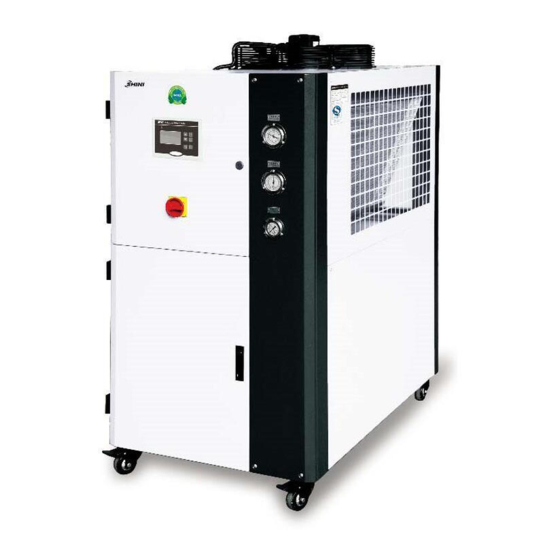
Please read through this operation manual before using and installation to avoid damage of the machine and personal injuries. SIC-A-R2 series are applicable for cooling molds to reduce products molding cycle, also they are available in the cooling of equipments in order to maintain a normal temperature. -
Page 10: Coding Principle
1.1 Coding Principle 1.2 Main Features 1) Standard configuration ● Cooling range 7~25℃. ● Stainless steel made insulted water tank. ● Anti-freezing thermostat. ● Adopt R410A refrigerant. ● Refrigeration loop controlled by high and low pressure switch. ● Compressor and pump overload relays. ●... - Page 11 Chapter 7, which contains service instructions intended for service engineers. Other chapters contain instructions for the daily operator. Any modifications of the machine must be approved by SHINI in order to avoid personal injury and damage to machine. We shall not be liable for any damage caused by unauthorized change of the machine.
-
Page 12: Technical Specifications
1.3 Technical Specifications 1.3.1 External Dimensions of SIC-A-R2 SIC-7.5A-R2~SIC-38A-R2 SIC-48A-R2~SIC-75A-R2 SIC-100A-R2~SIC-114A-R2 Picture 1-1: Outline Dimensional Drawing 12(96) -
Page 13: Table 1-1: Specifications
Table 1-1: Specifications Water Chilled Chilled Water Water Tank Weight Model Water Water Tank Tank (mm) (mm) (mm) (mm) (mm) (mm) Refill (kg) Inlet Outlet Outfall Overfall Port (inch) (inch) (inch) (inch) (inch) SIC-7.5A-R2 1200 1190 SIC-12A-R2 1490 1320 SIC-18A-R2 1430 1610 SIC-24A-R2... -
Page 14: Specification List
1.3.2 Specification List Table 1-2: Specification List Model SIC- 7.5A-R2 12A-R2 18A-R2 24A-R2 28A-R2 38A-R2 48A-R2 58A-R2 75A-R2 100A-R2 114A-R2 Item/ Parameters Refrigerant kW (50Hz/60Hz) 12 / 15 24 / 30 28 / 35.5 38 / 45 48 / 60 58 / 70 75 / 90 100 / 122... -
Page 15: Safety Regulations
2) Low pressure pump is for domestic and Southeast Asia export, customers can change for medium pressure pumps (use P for short; e.g.: SIC-and A-R2-P) or high pressure pumps (use HP for short; e.g.: SIC-and A-R2-HP), specific parameters in turn as shown above. 3) Pump power is included in total power. -
Page 16: Exemption Clause
Shini (including employees and agents). Shini is exempted from liability for any costs, fees, claims and losses caused by reasons below: 1. Any careless or man-made installations, operation and maintenances upon machines without referring to the Manual prior to machine using. -
Page 17: Structural Features And Working Principle
2. Structural Features and Working Principle 2.1 Main Functions SIC-A-R2 series are applicable for cooling molds to reduce products molding cycle, also they are available in the cooling of equipments in order to maintain a normal temperature. Besides, they are suitable for other industries with the need of cooling. - Page 18 Hot-air bypass function: the compressor continues working when the process water is cooled down to the required temperature, then the hot-air bypass valve opens as the temperature drops to its set value. A part of the refrigerant from the compressor passes through the bypass valve and then reach the evaporator, balancing out part of the machine refrigerating capacity and then goes back to the compressor without passing through the condenser.
-
Page 19: Parts Drawing
Parts Drawing 2.2.1 Structure Chart (SIC-7.5A-R2) Note: For details of the numbers in the parts drawing, please refer to the part list in 2.2.2 Picture 2-2:Structure Chart (SIC-7.5A-R2) 19(96) -
Page 20: Structure Chart Parts List (Sic-7.5A-R2)
2.2.2 Structure Chart Parts List (SIC-7.5A-R2) Table 2-1:Structure Chart Parts List (SIC-7.5A-R2) Name Parts No. Name Parts No. Movable black castor Braking black castor 3” YW03000300000 YW03000300200 3”PP Triangle support (left) Middle back beam Electric control cabinet Water tank support Right front stand stand Water tank Cover column... -
Page 21: Water System Diagram (Sic-7.5A-R2)
2.2.3 Water System Diagram (SIC-7.5A-R2) Note: For details of the numbers in the parts drawing, please refer to the part list in 2.2.4 Picture 2-3:Water System Diagram (SIC-7.5A-R2) 21(96) -
Page 22: Water System Parts List (Sic-7.5A-R2)
2.2.4 Water System Parts List (SIC-7.5A-R2) Table 2-2:Water System Parts List (SIC-7.5A-R2) Name Parts No. Name Parts No. Direct connection1” YW51000100000 Galvanized steel pipe 4 Street elbow 1” YW53100100000 Copper inserted core 1/2" BH12161200010 Galvanized steel Sluice valve1/2” YW50010200000 pipe 1 Floating ball valve YW59010200000 Pipe elbow 1”... -
Page 23: Refrigrant System Diagram (Sic-7.5A-R2)
2.2.5 Refrigrant System Diagram (SIC-7.5A-R2) Note: For details of the numbers in the parts drawing, please refer to the part list in 2.2.6 Picture 2-4:Refrigrant System Diagram (SIC-7.5A-R2) 23(96) -
Page 24: Refrigrant System Parts List (Sic-7.5A-R2)
2.2.6 Refrigrant System Parts List (SIC-7.5A-R2) Table 2-3:Refrigrant System Parts List (SIC-7.5A-R2) Name Parts No. Name Parts No. thermostatic expansion Hexbolt M8×50 YW60085000000 valve Flat washer 8 YW66082200100 Drying filter EK-053S YW85016530100 Spring washer8 YW65008000100 Evaporator Hexnut M8 YW64080600000 Air suction pipe Liquid pipe 2 Right condenser Refregrant indicator... -
Page 25: General Assembly Diagram (Sic-7.5A-R2)
2.2.7 General Assembly Diagram (SIC-7.5A-R2) Note: For details of the numbers in the parts drawing, please refer to the part list in 2.2.8 Picture 2-5:General Assembly Diagram (SIC-7.5A-R2) 25(96) -
Page 26: General Assembly Parts List (Sic-7.5A-R2)
2.2.8 General Assembly Parts List (SIC-7.5A-R2) Table 2-4:General Assembly Parts List (SIC-7.5A-R2) Name Parts No. Name Parts No. Liquid level indicator BL90006800020 Water pressure guage YW85001000100 cover Glass tube YW70963000000 Low pressure guage YW85003500000 Liquiid level BH12030000010 High pressure gauge YW85005500000 indicator STM-310 Level indicator... -
Page 27: Racking Diagram (Sic-12A-R2)
2.2.9 Racking Diagram (SIC-12A-R2) Note: For details of the numbers in the parts drawing, please refer to the part list in 2.2.10 Picture 2-6:Rack Diagram (SIC-12A-R2) 27(96) -
Page 28: Rack Parts List (Sic-12A-R2)
2.2.10 Rack Parts List (SIC-12A-R2) Table 2-5:Rack Parts List (SIC-12A-R2) Name Parts No. Name Parts No. Braking black castor YW03000300000 Movable black castor 3” YW03000300200 3” Fixed block of pressure Triangle support BL21000603020 switch Water tank Middle back beam Electric control cabinet Water tank cover support Left part of middle... -
Page 29: Water System Diagram (Sic-12A-R2)
2.2.11 Water System Diagram (SIC-12A-R2) Note: For details of the numbers in the parts drawing, please refer to the part list in 2.2.12 Picture 2-7:Water System Diagram (SIC-12A-R2) 29(96) -
Page 30: Water System Parts List (Sic-12A-R2)
2.2.12 Water System Parts List (SIC-12A-R2) Table 2-6:Water System Parts List (SIC-12A-R2) Name Parts No. Name Parts No. Floating ball YW59010200000 Direct connection 1/2” YW51001200000 valve1/2” Loosen joint 1” YW54000100000 Galvanized steel pipe 4 Galvanized steel Copper ferrule 1/2” BH12161200010 pipe 6 Galvanized steel T-connection 1/2”... -
Page 31: Refrigerant System Diagram (Sic-12A-R2)
2.2.13 Refrigerant System Diagram (SIC-12A-R2) Note: For details of the numbers in the parts drawing, please refer to the part list in 2.2.14 Picture 2-8:Refrigerant System Diagram (SIC-12A-R2) 31(96) -
Page 32: Refrigerant System Parts List (Sic-12A-R2)
2.2.14 Refrigerant System Parts List (SIC-12A-R2) Table 2-7:Refrigerant System Parts List (SIC-12A-R2) Name Parts No. Name Parts No. Thermostate expansion Hexbolt M8×50 YW60085000000 valve Flat washer 8 YW66082200100 Evaporator Spring washer 8 YW65008000100 Air suction pipe Hexnut M8 YW64080600000 Copper pipe 2 Solenoid valve Right condenser Exhuast pipe 1... -
Page 33: Rack Diagram (Sic-12A-R2)
2.2.15 Rack Diagram (SIC-12A-R2) Note: For details of the numbers in the parts drawing, please refer to the part list in 2.2.16 Picture 2-9:Rack Diagram (SIC-12A-R2) 33(96) -
Page 34: Rack Parts List (Sic-12A-R2)
2.2.16 Rack Parts List (SIC-12A-R2) Table 2-8:Rack Parts List (SIC-12A-R2) Name Parts No. Name Parts No. Refrigerant indicator BL90006800020 Water pressure gauge YW85001000100 cover Galss tube YW70963000000 Low pressure gauge YW85601800000 Refrigerant indicator BH12030000010 High pressure gauge YW85603800000 STM-310 Indicator screw BH12060700110 Upper door Indicator base... -
Page 35: Rack Diagram (Sic-18A-R2~24A-R2)
2.2.17 Rack Diagram (SIC-18A-R2~24A-R2) Note: For details of the numbers in the parts drawing, please refer to the part list in 2.2.18 Picture 2-10:Rack Diagram (SIC-18A-R2~24A-R2) 35(96) -
Page 36: Rack Parts List (Sic-18A-R2~24A-R2)
2.2.18 Rack Parts List (SIC-18A-R2~24A-R2) Table 2-9:Rack Parts List (SIC-18A-R2~24A-R2) Name Parts No. Name Parts No. Left front stand Hexbolt M8×20 YW60082000500 stand column Electric control Back beam cabinet Baffle palte of Pump angle iron condensor Fan guide Screw M6 Condenser cover Lower middle beam Back stand stand... -
Page 37: Water System Diagram (Sic-18A-R2~24A-R2)
2.2.19 Water System Diagram (SIC-18A-R2~24A-R2) Note: For details of the numbers in the parts drawing, please refer to the part list in 2.2.20 Picture 2-11:Water System Diagram (SIC-18A-R2~24A-R2) 37(96) -
Page 38: Water System Parts List (Sic-18A-R2~24A-R2)
2.2.20 Water System Parts List (SIC-18A-R2~24A-R2) Table 2-10:Water System Parts List (SIC-18A-R2~24A-R2) Name Parts No. Name Parts No. Wate pump Direct connection 1/2” YW51001200000 Galvanized steel pipe Copper cored valve 1/2” YW50010200100 Copper joint 1/2”PT Loosen joint 1-1/2” YW54001500000 BH12010400610 ×1/4”H Loosen joint 1-1/2”... -
Page 39: Refrigrant System Diagram (Sic-18A-R2~24A-R2)
2.2.21 Refrigrant System Diagram (SIC-18A-R2~24A-R2) Note: For details of the numbers in the parts drawing, please refer to the part list in 2.2.22 Picture 2-12:Refrigerant System Diagram (SIC-18A-R2~24A-R2) 39(96) -
Page 40: Refrigrant System Parts List (Sic-18A-R2~24A-R2)
2.2.22 Refrigrant System Parts List (SIC-18A-R2~24A-R2) Tabel 2-11:Refrigrant System Parts List (SIC-18A-R2~24A-R2) Name Parts No. Name Parts No. Thermostate Exhaust pipe 2 expansion valve Air suction pipe Liquid pipe 3 Liquid pipe1 Compressor Exhaust pipe 1 Screw M8 YW64080600000 Evaporator Spring washer 8 YW65008000100 Thermostate... -
Page 41: Genmeral Assembly Diagram (Sic-18A-R2~24A-R2)
2.2.23 Genmeral Assembly Diagram (SIC-18A-R2~24A-R2) Note: For details of the numbers in the parts drawing, please refer to the part list in 2.2.24 Picture 2-13:Genmeral Assembly Diagram (SIC-18A-R2~24A-R2) 41(96) -
Page 42: Genmeral Assembly Parts List (Sic-18A-R2~24A-R2)
2.2.24 Genmeral Assembly Parts List (SIC-18A-R2~24A-R2) Table 2-12:Genmeral Assembly Parts List (SIC-18A-R2~24A-R2) Name Parts No. Name Parts No. Refrigerant indicator YW20000000400 base Indicator screw BH12060700110 Water system Refrigerant indicator BH12030000010 Rack STM-310 Movable black castors Glass tube YW70963000000 YW03000300200 3”PP Indicator cover BL90006800020 Gauge plate... -
Page 43: Rack Diagram (Sic-28A-R2~38A-R2)
2.2.25 Rack Diagram (SIC-28A-R2~38A-R2) Note: For details of the numbers in the parts drawing, please refer to the part list in 2.2.26 Picture 2-14:Sack Diagram (SIC-28A-R2~38A-R2) 43(96) -
Page 44: Rack Parts List (Sic-28A-R2~38A-R2)
2.2.26 Rack Parts List (SIC-28A-R2~38A-R2) Table 2-13:Rack Parts List (SIC-28A-R2~38A-R2) Name Parts No. Name Parts No. Left front stand Refrigerant indicator stand column cover Left back stand stand Rear plate column Rear plate3 Lower side plate Right back stand Upper side palte on the stand column left Lower fan cover... -
Page 45: Water System & Refrigerant System Diagram (Sic-28A-R2~38A-R2)
2.2.27 Water System & Refrigerant system Diagram (SIC-28A-R2~38A-R2) Note: For details of the numbers in the parts drawing, please refer to the part list in 2.2.26 Picture 2-15:Water System & Refrigerant system Diagram (SIC-28A-R2~38A-R2) 45(96) -
Page 46: Water System & Refrigerant System Parts List (Sic-28A-R2~38A-R2)
2.2.28 Water System & Refrigerant system Parts List (SIC-28A-R2~38A-R2) Table 2-14:Water System & Refrigerant system Parts List (SIC-28A-R2~38A-R2) Name Stock No. Name Stock No. Outer joint 1”×2” YW57120100000 30 Copper pipe 8 Galvanized loosen joint 1” YW50000100000 31 Right condenser Galvanized loosen joint 2”... -
Page 47: Rack Diagram (Sic-48A-R2~75A-R2)
2.2.29 Rack Diagram (SIC-48A-R2~75A-R2) Note: For details of the numbers in the parts drawing, please refer to the part list in 2.2.30. Picture 2-16:Rack Diagram (SIC-48A-R2~75A-R2) 47(96) -
Page 48: Rack Parts List (Sic-48A~75A -R2)
2.2.30 Rack Parts List (SIC-48A~75A -R2) Table 2-15:Rack Parts List (SIC-48A~75A -R2) Name Stock No. Name Stock No. Baffle 1 Back stand column Right main stand Fixed welding piece of column side plate Right front stand Middle stand column column Rack middle layer Baffle 3 Base plate of... -
Page 49: Water System Diagram (Sic-48A-R2~75A-R2)
2.2.31 Water System Diagram (SIC-48A-R2~75A-R2) Note: For details of the numbers in the parts drawing, please refer to the part list in 2.232. Picture 2-17:Water System Diagram (SIC-48A-R2~75A-R2) 49(96) -
Page 50: Water System Parts List (Sic-48A-R2~75A-R2)
2.2.32 Water System Parts List (SIC-48A-R2~75A-R2) Table 2-16:Water System Parts List (SIC-48A-R2~75A-R2) Name Stock No. Name Stock No. Galvanized pipe inner Evaporator outlet 1 YW50000100000 joint 1” Galvanized pipe YW53000200100 Sluice valve 1” YW50000101000 elbow 2’’ Balck rubber pipe inner Evaporator outlet 2 YR60320500000 diameter 32... -
Page 51: Refrigerant System Diagram (Sic-48A-R2~75A-R2)
2.2.33 Refrigerant System Diagram (SIC-48A-R2~75A-R2) Note: For details of the numbers in the parts drawing, please refer to the part list in 2.2.34. Picture 2-18:Refrigerant System Diagram (SIC-48A-R2~75A-R2) 51(96) -
Page 52: Refrigerant Sytem Parts List (Sic-48A-R2~75A-R2)
2.2.34 Refrigerant Sytem Parts List (SIC-48A-R2~75A-R2) Table 2-17:Refrigerant Sytem Parts List (SIC-48A-R2~75A-R2) Name Stock No. Name Stock No. Compressor Front chiller by-pass 1 Back chiller liquid Solenoid valve pipe 1 Back chiller air Heat by-pass valve exhaust pipe 2 Right condenser Dryer filter YW85016400100 Base plate of... -
Page 53: General Assembly Disgram (Sic-48A-R2~75A-R2)
General Assembly Disgram 2.2.35 (SIC-48A-R2~75A-R2) Note: For details of the numbers in the parts drawing, please refer to the part list in 2.2.36. Picture 2-19:General Assembly Disgram (SIC-48A-R2~75A-R2) 53(96) -
Page 54: General Assemble Diagram Parts List (Sic-48A-R2~75A-R2)
General Assemble Diagram Parts List (SIC-48A-R2~75A-R2) 2.2.36 Table 2-18:General Assemble Diagram Parts List (SIC-48A-R2~75A-R2) Name Stock No. Name Stock No. Refrigerant indicator YW20000000400 Refrigerating system base Refrigerant indicator BH12060700110 Pressure gauge 0~10kg YW85001000100 Refrigerant indicator BH12030000010 Chilled water system Cross recessed oval head Glass tube YW70963000000 YW63063000000... -
Page 55: Rack Diagram (Sic-100A-R2)
2.2.37 Rack Diagram (SIC-100A-R2) Note: For details of the numbers in the parts drawing, please refer to the part list in 2.2.38. Picture 2-20:Rack Diagram (SIC-100A-R2) 55(96) -
Page 56: Rack Parts List (Sic-100A-R2)
2.2.38 Rack Parts List (SIC-100A-R2) Table 2-19:Rack Parts List (SIC-100A-R2) Name Stock No. Name Stock No. Rack base layer Left front brace Base plate of electrical Line jig fixed board cabinet Cross recessed oval YW62051500000 Electrical cabinet head screw M5×15 Middle water pond Brace 1 assembly 2... -
Page 57: Water System Diagram (Sic-100A-R2)
2.2.39 Water System Diagram (SIC-100A-R2) Note: For details of the numbers in the parts drawing, please refer to the part list in 2.2.40. Picture 2-21:Water System Diagram (SIC-100A-R2) 57(96) -
Page 58: Water System Parts List (Sic-100A-R2)
2.2.40 Water System Parts List (SIC-100A-R2) Table 2-20:Water System Parts List (SIC-100A-R2) Name Stock No. Name Stock No. Floating ball switch YW59010000000 Balck rubber pipe 3” YR60390300000 1” Water pipe 6 Water pipe 10 Water pipe 4 Pump Water pipe 9 Water pipe 2 Galvanizewd pipe T-joint Water pipe 1... -
Page 59: Refrigerant System Diagram (Sic-100A-R2)
2.2.41 Refrigerant System Diagram (SIC-100A-R2) Note: For details of the numbers in the parts drawing, please refer to the part list in 2.2.42. Picture 2-21:Refrigerant System Diagram (SIC-100A-R2) 59(96) -
Page 60: Refrigerant Sytem Parts List (Sic-100A-R2)
2.2.42 Refrigerant Sytem Parts List (SIC-100A-R2) Table 2-21:Refrigerant Sytem Parts List (SIC-100A-R2) Name Stock No. Name Stock No. Compressor Condenser baffle 3 Liquid pipe 3 Evaporator Air exhaust pipe 1 Air exhaust piep 5 Return air pipe 1 Liquid pipe 4 Liquid pipe 2 Air exhaust pipe 2 Air exhaust pipe 4... -
Page 61: General Assembly Disgram (Sic-100A-R2)
General Assembly Disgram 2.2.43 (SIC-100A-R2) Note: For details of the numbers in the parts drawing, please refer to the part list in 2.2.44. Picture 2-22:General Assembly Disgram (SIC-100A-R2) 61(96) -
Page 62: General Assembly Diagram Parts List (Sic-100A-R2)
2.2.44 General Assembly Diagram Parts List (SIC-100A-R2) Table 2-22:General Assemble Diagram Parts List (SIC-100A-R2) Name Stock No. Name Stock No. Rack Water pressure gauge YW85001000100 Side plate 2 Lower plate Side plate 1 Back plate 2 Back plate 3 Air guide Refrigerant indicator base YW20000000400 Refrigerant indicator... -
Page 63: Rack Diagram (Sic-114A-R2)
2.2.45 Rack Diagram (SIC-114A-R2) Note: For details of the numbers in the parts drawing, please refer to the part list in 2.2.46. Picture 2-23:Rack Diagram (SIC-114A-R2) 63(96) -
Page 64: Rack Parts List (Sic-114A-R2)
2.2.46 Rack Parts List (SIC-114A-R2) Table 2-23:Rack Parts List (SIC-114A-R2) Name Stock No. Name Stock No. Rack base layer Brace 2 Line jigf ixed board Left front stand column Cros-recessed oval Base plate of electrical YW62051500000 head screw M5×15 cabient Brace 1 Electrical cabinet Middle water pond... -
Page 65: Water System Diagram (Sic-114A-R2)
2.2.47 Water System Diagram (SIC-114A-R2) Note: For details of the numbers in the parts drawing, please refer to the part list in 2.2.48. Picture 2-24:Water System Diagram (SIC-114A-R2) 65(96) -
Page 66: Water System Parts List (Sic-114A-R2)
2.2.48 Water System Parts List (SIC-114A-R2) Table 2-24:Water System Parts List (SIC-114A-R2) Name Stock No. Name Stock No. Floating ball valve 1” YW59010000000 Black rubber pipe 3” YR60390300000 Water pipe 6 Water inlet flange Water pipe 4 Water pipe 1 Galvanized pipe T-joint Water pipe 9 YR52250100000... -
Page 67: Refrigerant System Diagram (Sic-114A-R2)
2.2.49 Refrigerant System Diagram (SIC-114A-R2) Note: For details of the numbers in the parts drawing, please refer to the part list in 2.2.50. Picture 2-25:Refrigerant System Diagram (SIC-114A-R2) 67(96) -
Page 68: Refrigerant Sytem Parts List (Sic-114A-R2)
2.2.50 Refrigerant Sytem Parts List (SIC-114A-R2) Table 2-25:Refrigerant System Parts List (SIC-114A-R2) Name Stock No. Name Stock No. Compresser Condenser baffle 3 Liquid pipe 3 Evaporator Air exhaust pipe 1 Air exhaust pipe 5 Return air pipe 1 Liquid pipe 4 Liquid pipe 2 Air exhaust pipe 2 Air exhaust pipe 4... -
Page 69: General Assembly Disgram (Sic-114A-R2)
General Assembly Disgram 2.2.51 (SIC-114A-R2) Note: For details of the numbers in the parts drawing, please refer to the part list in 2.2.52. Picture 2-26:General Assembly Disgram (SIC-114A-R2) 69(96) -
Page 70: General Assembly Diagram Parts List (Sic-114A-R2)
2.2.52 General Assembly Diagram Parts List (SIC-114A-R2) Table 2-26:General Assembly Diagram Parts List (SIC-114A-R2) Name Stock No. Name Stock No. Rack Water pressure gauge YW85001000100 Side plate 2 Lower door plate Side plate 1 Back plate 2 YM60650650000 Back plate 3 Air guide Refrigerant indicator base YW20000000400... -
Page 71: Main Parts And Functions
1) Compressing and conveying the refrigeration steam and forming low pressure in evaporator and high pressure in condenser, the compressor is the core of the whole system. 2) SIC-A-R2 adopts scroll compressor. Picture 2-27:Compressor 2.2.53.2 Condensor 1) Condenser is a heat output device which is used to discharge the heat absorbed by the evaporator and converted by the compressor to the cooling medium. -
Page 72: Picture 2-29:Drying Filter
1) The evaporator is the equipment which output the refrigerating capacity, in which the cooling agent absorb the heat of the cooled objects and achieve the aim of refrigeration. 2) SIC-A-R2 adopts adopts tube-in-shell horizontal evaporator. Picture 2-31:Evaporator 2.2.53.6 High and Low Pressure Controllers... -
Page 73: Picture 2-32:High And Low Pressure Controller
1) The high and low pressure controllers are used to control the working pressure of the compressor suction port and outlet port. 2) The pressure of the high pressure controller is set to 37 bar, and pressure of the low pressure controller is set to 4 bar. 3) Give an alarm when the pressure of the compressor outlet port is higher than 37 bar or the pressure of the compressor suction port is lower than 4 bar. -
Page 74: Picture 2-35:Heat By-Pass Valve
machine stops to prevent the compressor freezing. 2) Solenoid vlave is installed in front of the refrigerant indicator. 2.2.53.9 Heat By-pass Valve (optional) Picture 2-35:Heat By-pass Valve 1) Heat by-pass valve is used to bypass the cooling refrigerant when the temperature is low to prevent frequent starts and stops of the compressor and achieve accurate temperature control. - Page 75 2.2.53.11 Liquid Level Indicator (optional) Through the liquid level indicator, the water level in the tank can be viewd. 75(96)
-
Page 76: Main Electrical Components
2.3 Main Electrical Components 2.3.1 Thermal Overload Relay At delivery, the overload relay is set for manual reset (the reset button pointing to H). Manually reset the relay at the tripping off of the switch. When motor overload occurs, stop the machine. Check and solve the problem first. Then open the door of control box, press down the reset button of overload relay. -
Page 77: Installation And Debugging
3. Installation and Debugging Attention! Read this chapter before installation. Install the machine according to following steps! Air-cooled water chiller should be installed in an environment that has good ventilation, such as draughty area near the window. Ambient temperature should not be more than 43℃ if it is installed indoors. Use ventilator or exhaust pipe to conduct the hot air produced by the chiller to the outside. -
Page 78: Schematic Drawing Of Installation
11. Cooling tank 12. Oil Cooling Picture 3-1:Installation Location 3.3 Power Supply SIC-A-R2 series should be connected with 3φ 400V 50Hz power and earth wire and null wire. Attention! Before connecting the machine with power supply, please make sure that... -
Page 79: Application And Operation
Application and Operation Control Panel Picture 4-1:Control Panel Table 4-1:Specification of Control Panel Name Functions Remarks Note: Do not disassemble any Connect through power supply and turn electrical components or Power indicator on the main switch, the indicator will terminals in case of electrical become bright. - Page 80 Name Functions Remarks Check if the motor is blocked or the bearing is broken. If motor works normally, please check if the setting current of the overload relay in the control box is set too low. After the above measures are When pump current exceeds the limits, taken, wait for about 1 minute, Pump overload...
-
Page 81: Machine Startup
Machine startup 1) Turn on the main switch. Picture 4-2:Stepup Step 1 2) Turn on the pump. Type 50Hz 60Hz Model Medium High Medium High pressure pressure pressure pressure SIC-7.5A-R2 1.5~3.6 2.1~4.4 1.9~3.6 2.4~5.1 SIC-12A-R2 1.5~3.5 2.1~4.3 1.9~3.1 2.4~5.0 SIC-18A-R2 2.1~3.9 2.6~4.7 1.8~3.3... -
Page 82: Machine Shutdown
below 5℃). 5) Anti-freezing setting: anti-freezing switch equipped (setting value 5℃). When process water temperature is lower than 5℃, the compressor will stop working. Attention! Pump rotating direction should be correct. Attention! Before starting the system, make sure that cooling water pump is turned on. -
Page 83: Thermostat 1
evaporated.) 3) Turn off the main switch. Attention! Avoid electrical shock when main switch is turned on. Attention! In order to reduce the possibilities of machine damage and prolong the life, shut off the machine with correct methods. Thermostat 1 Picture 4-3:Thermostat 4.4.1 Temperature Setting Limits of SPL and SPH for setting points exist in any condition and set through... -
Page 84: Default Setting Table
4.4.2 Default Setting Table Table 4-2:Default Setting (SIC-7.5A~38A-R2) Code Meaning of parameters Default value Remark Unit: ℃ Setting value of output 1 Note: These parameters are only exclusive to AC1-5TSR2W-A. Table 4-3:Default Setting (SIC-48A~114A-R2) Code Meaning of parameters Default value Remark Unit: ℃... -
Page 85: Condenser And Evaporator Cleaning Step
Condenser and Evaporator Cleaning Step 4.5.1 Tube-in-shell Condenser Cleaning 1. Ensure the float ball in water tank of the machine is closed, to prevent the detergent solution from getting into the water tank of the machine. 2. Connect pipeline with hoses according to above picture. 3. - Page 86 1. Connect chilling water inlet/outlet of machine with hoses according to above picture. 2. Bactericide and water (according to purchased bactericide mixing requirement for specific proportion) proportional to solution and pour into the water tank of machine, then start-up pump cleaning of the machine. 3.
-
Page 87: Trouble-Shooting
Trouble-shooting The action of the The possible fault Faults Solutions protection units analysis A. The power supply is not switched on B. The fuse wire of the A. Power on after checking 1. No power control loop is burned B. Check the protection loop supply The protection units C. - Page 88 The action od the The possible fault Faults Solutions protection units analysis A. The regrigerant is not A. Check the system pipeline enough. and weld pipeline, add B. The vanes of the refrigerant. 5. The high The protection units compressor are spoiled B.
- Page 89 The action of the The possible fault Faults Solutions protection units analysis A. The open scale of the expansion valve is too A. Adjust the open scale of the 9. The chassis small expansion valve properly of the air B. The refrigerant is too B.
-
Page 90: Maintenance And Repair
Maintenance and Repair 90(96) - Page 91 Attention! All repair work should be done by qualified personnel only to avoid damage to the machine or personnel injury. In order to operate the machine rightly and safely, please caution the matter follows: 1) Do not turn off the main power switch to stop the machine, except emergency situation.
-
Page 92: Fill In The Refrigerant
check the reason of the failures, do not force the machine on before remove the failures. 3) Please check periodicaly to prolong the life of the machine and prevent the safety accident to appear. 4) Water supply should be processed, because the high PH can corrode the copper pipe acute. -
Page 93: Components Maintenance
6.2 Components Maintenance 6.2.1 Condenser SIC-A-R2 series water chiller use the air cooled fin style condenser which installed openly, in the using time, it is hard to avoid any dust and sundries, which will influence the heat emission effect, so it is necessary to clean the condenser at fixed periods in order to keep its working performance. -
Page 94: Evaporator
Attention! Do the cleaning work every half-year in the environment with little dust, but you must do the work every month in the environment with a great deal of dusts, and under the severe environment you had better see the situation to do the work. -
Page 95: Maintenance Schedule
6.3 Maintenance Schedule About the Machine 6.3.1 Model Production date Ф Voltage V Frequency Total power 6.3.2 Check after Installation Check the pipes are all correctly connected. Check if there are leakages in the piping system. Check if there are breaks in welding joint. Electrical Installation Voltage: Fuse specification: 1 Phase... -
Page 96: Half-Yearly Checking
Check whether condenser is under blockage. 6.3.7 Half-yearly Checking Check and clean the condenser and evaporator. Check and clean the filter and expansion valve. Check system performance. Clean condenser. 6.3.8 Yearly Checking Check whether the contactor is normal. 6.3.9 3 year Checking PC board renewal.
Need help?
Do you have a question about the SIC-A-R2 and is the answer not in the manual?
Questions and answers
when compressor turns on ,it makes a loud buzzing noise