
Related Manuals for Shini SICC-W Series


Summary of Contents for Shini SICC-W Series
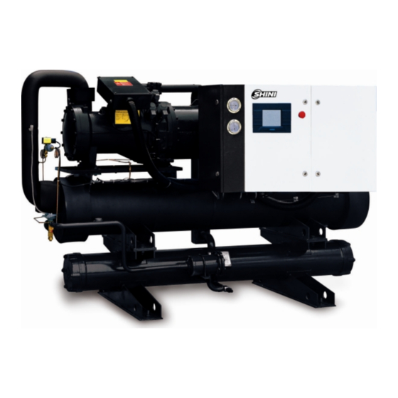
- Page 1 SICC-W Series Water-cooled Central Water Chiller Date: Apr, 2013 Version: Ver.B (English)
-
Page 3: Table Of Contents
Contents General Description .................. 7 1.1 Coding Principle ................... 8 1.2 Feature....................8 1.3 Technical Specifications..............10 1.3.1 SICC-W Dimensions..............10 1.3.2 Specification ................11 1.4 Safety Regulations ................15 1.4.1 Safety Signs and Labels ............15 1.4.2 Signs and Labels ..............15 1.5 Exemption Clause ................ - Page 4 Operation Guide ..................32 4.1 The General Introduction of Operational Interface ......32 4.1.1 Features Demonstration ............32 4.1.2 Safety Requirement ..............34 4.2 Unit Running ..................35 4.2.1 Start Interface ................35 4.2.2 Main Running Interface............36 4.2.3 Setup interface ................ 36 4.2.4 User Setup Interface..............
- Page 5 6.2.7 Check Half-yearly ..............53 6.2.8 Yearly Checking............... 53 6.2.9 3 year Checking............... 53 Table Index Table 1-1:Specification of SICC-W Single Compressor R22......11 Table 1-2:Specification of SICC-W Single Compressor R134a...... 12 Table 1-3:Specification of SICC-W Double Compressor R22 ......13 Table 1-4:Specification of SICC-W Double Compressor R134a ....
- Page 6 Picture 4-6:Status Inquiry Interface ..............38 Picture 4-7:Hourly Curve Window ..............39 Picture 4-8:History Window................39 Picture 4-9:History Record Interface .............. 40 Picture 4-10:Operation Instruction Interface........... 40 Picture 4-11:Fault Inquiry Interface ..............41 Picture 4-12:Time Setup ................42 Picture 4-13:Contrast Setup................43 6(53)
-
Page 7: General Description
Read this manual carefully before operation to prevent damage of the machine or personal injuries. SICC-W series water applicable for cooling moulds to reduce products molding cycle, also they are available in the cooling of equipments in order to maintain a normal temperature. -
Page 8: Coding Principle
First Three Codes: Refrigerating Ccapacity (kW) Fourth Code: W=Water Cooled Fifth Code: S=Single Compressor D=Double Compressors Shini Central Water Chillers 1.2 Feature ● German-made twin screw compressor with longer service life. ● Stepless compressor output capacity adjusting function are designed to save power. - Page 9 Chapter 6, which contains service instructions intended for service engineers. Other chapters contain instructions for the daily operator. Any modifications of the machine must be approved by SHINI in order to avoid personal injury and damage to machine. We shall not be liable for any damage caused by unauthorized change of the machine.
-
Page 10: Technical Specifications
1.3 Technical Specifications 1.3.1 SICC-W Dimensions Picture 1-1:SICC-W Dimensions (One Compressor) Picture 1-2:SICC-W Dimensions (Two Compressors) 10(53) -
Page 11: Specification
1.3.2 Specification Table 1-1:Specification of SICC-W Single Compressor R22 Note: 1) Parameter test condition: chilled water flow 0.172m /(h.kW); chilled water outlet temperature 7 ; ℃ cooling water inlet temperature 30 ;cooling water flow 0.215m /(h.kW) ℃ 2) The noise level is tested at 1 meter in front of and 1.5 meter above the machine. 3) As per application needs, stepless compressor output capacity adjusting function can be optionally available. - Page 12 Table 1-2:Specification of SICC-W Single Compressor R134a Note: 1) Parameter test condition: chilled water flow 0.172m /(h.kW); chilled water outlet temperature 7℃; cooling water inlet temperature 30℃; cooling water flow 0.215m /(h.kW). 2) The noise level is tested at 1 meter in front of and 1.5 meter above the machine. 3) As per application needs, stepless compressor output capacity adjusting function can be optionally available.
- Page 13 Table 1-3:Specification of SICC-W Double Compressor R22 Note: 1) Parameter test condition: chilled water flow 0.172m /(h.kW);chilled water outlet temperature 7℃; cooling water inlet temperature 30℃; cooling water flow 0.215m /(h.kW). 2) The noise level is tested at 1 meter in front of and 1.5 meter above the machine. 3) As per application needs, stepless compressor output capacity adjusting function can be optionally available.
- Page 14 Table 1-4:Specification of SICC-W Double Compressor R134a Note: 1) The refrigerant capacity is tested under conditions that process water inlet temp. is at 12℃, process water outlet temp. is at 7℃, cooling water inlet temp. is at 30℃ and cooling water outlet temp. is at 35℃.
-
Page 15: Safety Regulations
1.4 Safety Regulations Strictly abide by the following safety regulations to prevent damage of the machine or personal injuries. 1.4.1 Safety Signs and Labels The installation of electrical devices should be conducted by professional electricians. During repairing and maintenance, must turn off the main switch and control switch. - Page 16 Shini (including employees and agents). Shini is exempted from liability for any costs, fees, claims and losses caused by reasons below: 1. Any careless or man-made installations, operation and maintenances upon machines without referring to the Manual prior to machine using.
-
Page 17: Structure Characteristics And Working Principle
Structure Characteristics and Working Principle 2.1.1 Working Principle of SICC-W Single Unit Series The SICC-W water-cooled central water chiller is mainly made up of four components which are compressor, condenser, thermostatic expansion valve and evaporator. It uses single stage vapor compression refrigeration system, and takes the advantage of the mechanism of transformation between gas and liquid status for absorbing and releasing heat by using of refrigerant to achieve the effectiveness of refrigeration. -
Page 18: Working Principle Of Sicc-W Double Unit Series
2.1.2 Working Principle of SICC-W Double Unit Series The SICC-W water-cooled central water chiller is mainly made up of four components which are compressor, condenser, thermostatic expansion valve and evaporator. It uses single stage vapor compression refrigeration system, and takes the advantage of the mechanism of transformation between gas and liquid status for absorbing and releasing heat by using of refrigerant to achieve the effectiveness of refrigeration. -
Page 19: Assembly Drawing
2.2 Assembly Drawing 2.2.1 Structure Drawing of SICC-W Single Unit Names of Parts: 1. Compressor 2. PLC control panel 3. Electrical control box 4. Nameplate of the unit 5. Condenser 6. Expansion valve 7. Evaporator 8. Cold water inlet 9. Cold water outlet 10. -
Page 20: Structure Drawing Of Sicc-W Double Unit
2.2.2 Structure Drawing of SICC-W Double Unit Names of Parts: 1. Compressor 2. PLC control panel 3. Nameplate of the unit 4. Expansion valve 5. Electricalcontrolbox 6. Cold water outlet 7. Cold water inlet 8. Cold water outlet 9. Cold water inlet 10. -
Page 21: Electrical Diagram
2.3 Electrical Diagram 2.3.1 SICC-W Single System / Bitzer Compressor / Part Winding Start Picture 2-5:SICC-W Single System / Bitzer Compressor / Part Winding Start 21(53) -
Page 22: Sicc-W Single System / Bitzer Compressor / Star-Delta Start
2.3.2 SICC-W Single System / Bitzer Compressor / Star-delta Start Picture 2-6:SICC-W Single System / Bitzer Compressor / Star-delta Start 22(53) -
Page 23: Sicc-W Double System / Bitzer Compressor / Part Winding Start
2.3.3 SICC-W Double System / Bitzer Compressor / Part Winding Start Picture 2-7:SICC-W Double System / Bitzer Compressor / Part Winding Start 23(53) -
Page 24: Sicc-W Double System / Bitzer Compressor / Star-Delta Start24
2.3.4 SICC-W Double System / Bitzer Compressor / Star-delta Start Picture 2-8:SICC-W Double System / Bitzer Compressor / Star-delta Start 24(53) -
Page 25: Installation And Debugging
Installation and Debugging Please read this chapter carefully before installation, and you must install the machine according to the following procedures! Before installing the chiller, please design the pipe system reasonably, lay out the position of injection mould machine and cooling water tower to make the repair and maintenance convenient, the installation of chiller should be convenient to operate and keep appropriate distance from cooling water tower. -
Page 26: Water Pipe Installation
9) The pipeline diameter of cooling water tower and circulating pump should be no less than that of the connection tube of condenser (the installation of ingress and egress pipeline system should comply with the assembly line diagram). When perform long distance transportation the heavy caliber water pipe should be used for connecting the cooling water. - Page 27 inorder to make the water flow rate in each exchanger maintain the same, and to avoid bias current phenomena, try to make the shuttle water pipe resistance from chiller to every heat exchanger all the same. 4) Adopts sealed loop water system to buffer the water volume expansion or shrink phenomina and insulate the backup water pressure to water pipe's impact.
-
Page 28: Select The Installation Site
13) Install water pipes for chiller, evaporator or cooling water as the following figure 3-2 shows: Picture 3-2:Waterpipe Installation for the Water Chilling System 3.3 Select the Installation Site 1) Select the floor which can fully support the unit running weight, the intensity of the ground needs to be reinforced and makes it uneasy to cause resonance and noise. -
Page 29: Bearing Base
Picture 3-3:Select the Installation Site 3.4 Bearing Base 1) The foundation of the concrete base, according to the operation weight of the machines, will put on steel bars, diameter above 9.5 mm(#3), and are clustered together on the upper and lower layer of the base, inter spaced about 10 cm. -
Page 30: The Overhead Hoisting Of The Unit
3.5 The Overhead Hoisting of the Unit 1) Propose plans of overhead hoisting before practise, including entering date for each unit. Dimensions of appearance. Weight, path, reserved holes, hanging and transporting device as well. Items Check points 1. Check aisle, stair gate and transporting path. Path 2. -
Page 31: Power Connection
Check the specification of the electricity supply to see if it matches with that of the demand. For SICC-W series, the specification of power is AC 3Φ 400V type. We can also manufacture according to client′s special demand. The ground wire must be connected to when connect to the power. -
Page 32: Operation Guide
Before operation, please open valves on the system circuit to avoid low/ high pressure alarm. The General Introduction of Operational Interface SICC-W series controller is an programmable controller which adopts double micro-processor technology applicable to air conditioned refrigeration area. It can edit programme according to client's demand, and makes the air-conditioner system run in its best status. - Page 33 4) Adopts 485 communication and transmission technology by which the data transmission distance can reach 1200 meters without any signal decrease. The communication distance can reach above 3000 meters after adding one repeater. 5) Install 16 modules at most on Rs485 communication BUS. 6) Convenient communication connection way which easily realize the data communication between main and auxiliary board by a single phone line.
-
Page 34: Safety Requirement
curve. 18) Can inquire present fault and history fault record and has fault statistic function which can be used to analyse the unstable parts of the machine so to ameliorate it. It can inquire the history fault record according to fault number, fault times or fault ocurring time. -
Page 35: Unit Running
Unit Running 4.2.1 Start Interface Picture 4-2:Start Interface The microcomputer will display start interface in 10 seconds after connected to power. 1) The manufacturer can enter into the manufacturer setup interface by inputing the right password; method: touch the upper central position of the manufacturer logo to get a pop up for password entering, then input the right password to get into. -
Page 36: Main Running Interface
4.2.2 Main Running Interface Picture 4-3:Main running interface Press "start" or "stop" key to start or stop the unit. The water chiller unit displays: "the outlet water temp. "and "the inlet water temp." (Note: if it is multi-modules running, the outlet water and inlet water temperatures are for that of the system's) the five lines from the left side display;... -
Page 37: User Setup Interface
Picture 4-4:Setup Interface Notice! When【pressure sensor】is not set to be "not in use", it will display "pressure sensor parameter settings". 4.2.4 User Setup Interface Press "user setup" key in the main running interface, input the right password to get into user setup interface, like the following figure shows: press "page up" or "page down"... -
Page 38: Status Inquiry Interface
Notice! Only when use air-cooled heat pump or out circulating pump that set manual mode to heat, it will display "item 8: forced action"; or it will not display anything and can not do any manual operation. 4.2.5 Status Inquiry Interface Press "status inquiry"... -
Page 39: History Record Interface
Notice! Status may vary according to different model and it is related to the using setup of temperature probe. Picture 4-7:Hourly Curve Window Picture 4-8:History Window 4.2.6 History Record Interface 39(53) -
Page 40: Operation Instruction Interface
Press "history record" key at the main running interface to enter into history record inquiry interface, including fault inquiry and accumulated running hours for the compressor, as the following figure shows: press "page up" or "page down" to shift the inquiry item, press "enter" key to get into the selected inquiry item. -
Page 41: Fault Inquiry Interface
4.2.8 Fault Inquiry Interface The "fault inquiry" key is hiden, when new fault occurs, the "fault inquiry" key at the main running interface is twinkling and alarming, press "fault inquiry" key to enter into fault inquiry interface, as the following figure shows: press"silencer" key to stop alarming sound, press "reset"... -
Page 42: Weekly Timing Setup
Items Setup contents Instruction Refer to control logic for detail and can not be set when Running mode: Cooling/heating the unit is running. Control temp.: 12℃ Only Visible when cooling. Control temp.: 25℃ Only visible when heating. Weekly timing: Invalid Only effective when set into valid weekly timing. -
Page 43: Contrast Setup
Set user time, that is to say interface displaying time and this setup will not affect the system time (refer to expire date setup). Set two numbers at one time, continuously press two number key to complete the setup and press "enter' key to setup the next item while press "return"... -
Page 44: Maintenance
2. Timing start/stop Setup the timing set parameter in the user's parameter setup item list, time set one time start/stop time; if it is working, then the unit will stop at that time; if it is being stopped, then the unit will start at that time. 4.3.9 Maintenance 1. - Page 45 its privilege is only inferior to manufacturer code, which can be used to enter into machine and user settings to modify the relevant setups. c) User set password is usually possessed by final user and can be only used to modify user parameter settings.
-
Page 46: Trouble-Shooting
Trouble-shooting Faults Name of faults Solution Remark Deficient in cooling Stop compressor, cooling If it is first plate, stop system if it PCB-? waterflow and freezing pump is other plate, stop module Deficient in cooling Stop compressor, cooling PCB-? Remark instruction waterflow pump Fan in cooling tower is... - Page 47 Faults Name of faults Solution Remark The circuit for temp. PCB-? Stop compressor probe of air vent breaks The circuit for temp. PCB-? Stop compressor probe of air vent shorts Overlow temp. for the out PCB-? Stop compressor water Overhigh temp. for air PCB-?...
-
Page 48: Maintenance And Repair
Maintenance and Repair Because impurities in the water inevitably deposited on the condenser wall, the condenser water flow will become smaller and smaller with the increase of deposition of impurities. And the efficiency of heat transfer will be getting lower and lower. -
Page 49: Maintenance Ltems
2) When the machine stops due to faults, press down the main power switch first (the alarming light goes out), then check the cause of the faults, the machine should not be started forcibly before troubleshooting. 3) Do regular inspection inorder to prolong the lifespan of the system and avoid the happening of accidents. - Page 50 Qualification Maintenance item Times Remark standard(treatment) Start moment, when running or Noise Any time stop, there is no abnormal sound Measure it with DV500V high Insulative 1time/year resistance meter and should reach resistance 10MΩ Anti-vibration Touch with finger and the one with 1time/year rubber is aging elasticity is qualified...
- Page 51 Qualification Maintenance item Times Remark standard(treatment) Pressure To make comparison with right Action 1time/half year gauge pressure gauge Every operating Action 1time/month The fluent close action valve electrical leak Use leak detector to detect the unit detector Refrigerant itself and its tube connection part to or blast 1time/month leakage...
-
Page 52: Maintenance Schedule
6.2 Maintenance Schedule 6.2.1 About the Machine Model Manufacture date Voltage Ф Frequency Power 6.2.2 Installation & Inspection Check if the pipe are connected correctly Check if the pipe has any leakage Check if the sealed joint has any crack Electrical component installation Voltage: Fuse melting current: 1 Phase... - Page 53 6.2.7 Check Half-yearly Check and clean filter and expansion valve. Check the whole machine condition. Clean condenser. 6.2.8 Yearly Checking Check whether the contactor is normal. 6.2.9 3 year Checking PC board renewal. No fuse breaker renewal. 53(53)
Need help?
Do you have a question about the SICC-W Series and is the answer not in the manual?
Questions and answers