Vega VEGASON 63 Quick Setup Manual
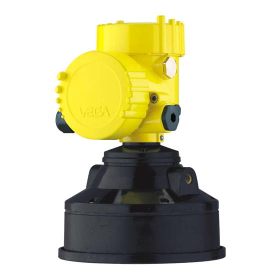
Ultrasonic sensor for continuous level measurement
Hide thumbs
Also See for VEGASON 63:
- Operating instructions manual (52 pages) ,
- Operating instructions manual (64 pages)

Subscribe to Our Youtube Channel
Related Manuals for Vega VEGASON 63


Summary of Contents for Vega VEGASON 63
- Page 1 Quick setup guide Ultrasonic sensor for continuous level measurement VEGASON 63 Four-wire 4 … 20 mA/HART Document ID: 51864...
-
Page 2: Table Of Contents
Operating Instructions Manual as well as the Safety Manual that comes with instruments with SIL qualification. These manuals are available on our homepage. Operating instructions VEGASON 63 - 4 … 20 mA/HART - Four- wire: Document-ID 28780 Editing status of the quick setup guide: 2021-06-15 VEGASON 63 • Four-wire 4 … 20 mA/HART... -
Page 3: For Your Safety
During work on and with the device, the required personal protective equipment must always be worn. Appropriate use VEGASON 63 is a sensor for continuous level measurement. You can find detailed information about the area of application in chapter " Product description". Operational reliability is ensured only if the instrument is properly used according to the specifications in the operating instructions manual as well as possible supplementary instructions. -
Page 4: Namur Recommendations
That is why we have introduced an environment management system with the goal of continuously improving company environmental pro- tection. The environment management system is certified according to DIN EN ISO 14001. Please help us fulfil this obligation by observing the environmental instructions in this manual: • Chapter " Packaging, transport and storage" • Chapter " Disposal" VEGASON 63 • Four-wire 4 … 20 mA/HART... -
Page 5: Product Description
Serial number Move to " www.vega.com" and enter in the search field the serial number of your instrument. Alternatively, you can access the data via your smartphone: • Download the VEGA Tools app from the " Apple App Store" or the " Google Play Store" • Scan the DataMatrix code on the type label of the instrument or •... -
Page 6: Mounting
Fig. 1: Minimum distance to the max. level blocking distance Reference plane Mounting Mount the sensor at least 200 mm (7.874 in) away from the vessel wall. > 200 mm Fig. 2: Mounting on round vessel tops Reference plane Vessel center or symmetry axis VEGASON 63 • Four-wire 4 … 20 mA/HART... -
Page 7: Connecting To Power Supply
11. Connect the lead cable for power supply in the same way accord- ing to the wiring plan, in addition connect the ground conductor to the inner ground terminal. 12. Screw the housing lid back on The electrical connection is finished. VEGASON 63 • Four-wire 4 … 20 mA/HART... -
Page 8: Wiring Plan, Double Chamber Housing
4 Connecting to power supply Wiring plan, double chamber housing Wiring plan 4...20mA L1 N 4 ... 20 mA Fig. 4: Wiring plan - double chamber housing Voltage supply Signal output VEGASON 63 • Four-wire 4 … 20 mA/HART... -
Page 9: Set Up With The Display And Adjustment Module Plicscom
Setup steps Set parameters 1. Go to the menu " Basic adjustment" via the display and adjust- ment module. VEGASON 63 • Four-wire 4 … 20 mA/HART... - Page 10 The actual level is then calculated on the basis of these entered values. At the same time, the operating range of the sensor is limited from maximum range to the requested range. VEGASON 63 • Four-wire 4 … 20 mA/HART...
- Page 11 3. Confirm " False signal suppression - Change now" with [OK] and select in the below menu " Create new". Enter the actual distance from the sensor to the medium surface. All false signals in this area are detected by the sensor and saved after confirming with [OK]. VEGASON 63 • Four-wire 4 … 20 mA/HART...
-
Page 12: Menu Schematic
Sensor-TAG Linear Sensor Display Basic adjustment ▶ Display Diagnostics Service Info Displayed value Display unit Scaling Backlight ► Scaled Volume 0 % = 0.0 m³ Switched off m³ 100 % = 100.0 m³ VEGASON 63 • Four-wire 4 … 20 mA/HART... - Page 13 Copy sensor data? Enable? Address 0 Info Basic adjustment Display Diagnostics Service ▶ Info Instrument type Date of manufacture Last change using PC Sensor characteristics Software version Display now? Serial number 12345678 VEGASON 63 • Four-wire 4 … 20 mA/HART...
-
Page 14: Set Up With Smartphone/Tablet, Pc/Notebook Via Bluetooth
PIN in the adjustment menu of the sensor, e.g. to " 1111": 1. In the adjustment menu, go to " Service", " PIN": Basic adjustment Display Diagnostics ▶ Service Info Enable? 2. Change sensor PIN and confirm with " OK": 0000 VEGASON 63 • Four-wire 4 … 20 mA/HART... -
Page 15: Connecting
Bluetooth-capable instru- ments in the area. PC/Notebook Start PACTware and the VEGA project assistant. Select the device search via Bluetooth and start the search function. The device auto- matically searches for Bluetooth-capable devices in the vicinity. -
Page 16: Sensor Parameter Adjustment
For authentication, enter in the next menu window the 4-digit sensor PIN. Sensor parameter adjustment The sensor parameterization is carried out via the adjustment app on the smartphone/tablet or the DTM on the PC/notebook. App view Fig. 8: Example of an app view - Setup sensor adjustment VEGASON 63 • Four-wire 4 … 20 mA/HART... -
Page 17: Supplement
Cable entry Ʋ Double chamber housing – 1 x cable gland M20 x 1.5 (cable: ø 5 … 9 mm), 1 x blind plug M20 x 1.5; plug M12 x 1 for VEGADIS 61 (optional) – 1 x closing cap ½ NPT, 1 x blind plug ½ NPT, plug M12 x 1 for VEGADIS 61 (optional) – 1 x plug (depending on the version), 1 x blind plug M20 x 1.5; plug M12 x 1 for VEGADIS 61 (optional) Spring-loaded terminals for wire cross- < 2.5 mm² (AWG 14) section Voltage supply Operating voltage Ʋ Non-Ex and Ex-d instrument 20 … 72 V DC, 20 … 253 V AC, 50/60 Hz Power consumption max. 4 VA; 2.1 W VEGASON 63 • Four-wire 4 … 20 mA/HART... - Page 18 Notes VEGASON 63 • Four-wire 4 … 20 mA/HART...
- Page 19 Notes VEGASON 63 • Four-wire 4 … 20 mA/HART...
- Page 20 Subject to change without prior notice © VEGA Grieshaber KG, Schiltach/Germany 2021 VEGA Grieshaber KG Am Hohenstein 113 Phone +49 7836 50-0 77761 Schiltach E-mail: info.de@vega.com...
Need help?
Do you have a question about the VEGASON 63 and is the answer not in the manual?
Questions and answers