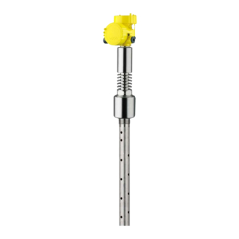
Vega VEGAFLEX 86 Quick Setup Manual
Tdr sensor for continuous level and interface measurement of liquids
Hide thumbs
Also See for VEGAFLEX 86:
- Operating instructions manual (104 pages) ,
- Quick setup manual (16 pages) ,
- Operating instruction (92 pages)
Table of Contents

Related Manuals for Vega VEGAFLEX 86


Summary of Contents for Vega VEGAFLEX 86
- Page 1 Quick setup guide TDR sensor for continuous level and interface measurement of liquids VEGAFLEX 86 Modbus and Levelmaster protocol Converter version in second chamber Coax probe -196 … +280 °C -196 … +450 °C Document ID: 47614...
-
Page 2: Table Of Contents
Operating Instructions Manual as well as the Safety Manual that comes with instruments with SIL qualification. These manuals are available on our homepage. Operating instructions VEGAFLEX 86 - Modbus and Levelmas- ter protocol - Coax probe, -196 … +280 °C / -196 … +450 °C: Document-ID 42288 Editing status of the quick setup guide: 2023-05-23... -
Page 3: For Your Safety
All operations described in this documentation must be carried out only by trained, qualified personnel authorised by the plant operator. During work on and with the device, the required personal protective equipment must always be worn. Appropriate use VEGAFLEX 86 is a sensor for continuous level measurement. You can find detailed information about the area of application in chapter " Product description". Operational reliability is ensured only if the instrument is properly used according to the specifications in the operating instructions manual as well as possible supplementary instructions. -
Page 4: Namur Recommendations
That is why we have introduced an environment management system with the goal of continuously improving company environmental pro- tection. The environment management system is certified according to DIN EN ISO 14001. Please help us fulfil this obligation by observing the environmental instructions in this manual: • Chapter " Packaging, transport and storage" • Chapter " Disposal" VEGAFLEX 86 • Modbus and Levelmaster protocol... -
Page 5: Product Description
Move to " www.vega.com" and enter in the search field the serial number of your instrument. Alternatively, you can access the data via your smartphone: • Download the VEGA Tools app from the " Apple App Store" or the " Google Play Store" • Scan the QR-code on the type label of the device or VEGAFLEX 86 • Modbus and Levelmaster protocol... - Page 6 2 Product description • Enter the serial number manually in the app VEGAFLEX 86 • Modbus and Levelmaster protocol...
-
Page 7: Mounting
Keep in mind that measurement all the way down to the tip of the probe may not be pos- sible. The exact value of the min. distance (lower blocking distance) is stated in chapter " Technical data". Fig. 2: Vessel with conical bottom VEGAFLEX 86 • Modbus and Levelmaster protocol... -
Page 8: Connecting To Power Supply And Bus System
6. Insert the wire ends into the terminals according to the wiring plan Note: Solid cores as well as flexible cores with wire end sleeves are insert- ed directly into the terminal openings. In case of flexible cores without end sleeves, press the terminal from above with a small screwdriver, the terminal opening is then free. When the screwdriver is released, the terminal closes again. 7. Check the hold of the wires in the terminals by lightly pulling on them 8. Connect the shielding to the internal ground terminal, connect the external ground terminal to potential equalisation VEGAFLEX 86 • Modbus and Levelmaster protocol... -
Page 9: Wiring Plan
Fig. 5: Connection compartment USB interface 2 Slide switch for integrated termination resistor (120 Ω) Modbus signal Voltage supply Terminal Function Polarity Voltage supply Voltage supply Modbus signal D0 Modbus signal D1 Function ground when installing ac- cording to CSA (Canadian Standards Association) VEGAFLEX 86 • Modbus and Levelmaster protocol... -
Page 10: Set Up The Sensor With The Display And Adjustment Module
3. Screw housing lid with inspection window tightly back on Disassembly is carried out in reverse order. The display and adjustment module is powered by the sensor, an ad- ditional connection is not necessary. Fig. 6: Insertion of the display and adjustment module Note: If you intend to retrofit the instrument with a display and adjustment module for continuous measured value indication, a higher lid with an inspection glass is required. VEGAFLEX 86 • Modbus and Levelmaster protocol... -
Page 11: Parameter Adjustment - Quick Setup
The distance refers to the sensor reference plane (seal surface of the process fitting). Keep in mind that the max. level must lie below the blocking distance. Min. adjustment In this menu item, you can enter the min. adjustment for the level. Enter the suitable distance value in m for the empty vessel (e.g. distance from the flange to the probe end) corresponding to the per- centage value. The distance refers tot he sensor reference plane (seal surface of the process fitting). VEGAFLEX 86 • Modbus and Levelmaster protocol... - Page 12 False signal suppression High nozzles and internal vessel installations cause interfering reflec- tions and can influence the measurement. A false signal suppression detects, marks and saves these false signals so that they are no longer taken into account for the level and interface measurement. We generally recommend carrying out a false VEGAFLEX 86 • Modbus and Levelmaster protocol...
- Page 13 All interfering signals in this section are detected by the sensor and stored. The instrument carries out an automatic false signal suppression as soon as the probe is uncovered. The false signal suppression is always updated. VEGAFLEX 86 • Modbus and Levelmaster protocol...
-
Page 14: Setup With Smartphone/Tablet (Bluetooth)
The menu item " PIN" is only displayed if in the menu " Setup", " Lock/ Unlock adjustment" the adjustment is released. 2. Change sensor PIN Note: Bluetooth access can only be established if the current sensor PIN differs from the default setting " 0000". It is possible both when the VEGAFLEX 86 • Modbus and Levelmaster protocol... -
Page 15: Connecting
Start the adjustment app and select the function "Setup". The smart- phone/tablet searches automatically for Bluetooth-capable instru- ments in the area. PC/Notebook Start PACTware and the VEGA project assistant. Select the device search via Bluetooth and start the search function. The device auto- matically searches for Bluetooth-capable devices in the vicinity. Connecting The message "... -
Page 16: Supplement
0.2 … 2.5 mm² (AWG 24 … 14) Ʋ Stranded wire with end sleeve 0.2 … 1.5 mm² (AWG 24 … 16) Voltage supply Operating voltage 8 … 30 V DC Max. power consumption 520 mW Reverse voltage protection Integrated VEGAFLEX 86 • Modbus and Levelmaster protocol... - Page 17 Notes VEGAFLEX 86 • Modbus and Levelmaster protocol...
- Page 18 Notes VEGAFLEX 86 • Modbus and Levelmaster protocol...
- Page 19 Notes VEGAFLEX 86 • Modbus and Levelmaster protocol...
- Page 20 Subject to change without prior notice © VEGA Grieshaber KG, Schiltach/Germany 2023 VEGA Grieshaber KG Am Hohenstein 113 Phone +49 7836 50-0 77761 Schiltach E-mail: info.de@vega.com...
Need help?
Do you have a question about the VEGAFLEX 86 and is the answer not in the manual?
Questions and answers