
Related Manuals for Omega OS-MINI Series


Summary of Contents for Omega OS-MINI Series
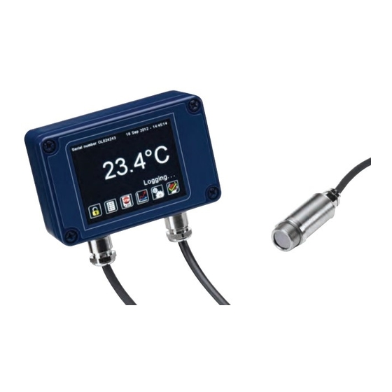
- Page 1 User’s Guide Shop online at omega.com e-mail: info@omega.com For latest product manuals: omega.com/en-us/pdf-manuals Miniature Fixed Infrared Sensor with Optional Touch Screen Display...
- Page 2 Fax: (203) 359-7700 e-mail: info@omega.com For Other Locations Visit omega.com/worldwide The information contained in this document is believed to be correct, but OMEGA accepts no liability for any errors it contains, and reserves the right to alter specifications without notice.
- Page 3 The OS-Mini and OS-Mini22 are a range of miniature, non-contact infrared temperature sensors with separate electronics modules. All OS-Mini models have an adjustable emissivity setting and are capable of measuring a wide variety of target materials, including food, paper, textiles, plastics, leather, tobacco, pharmaceuticals, chemicals, rubber, coal and asphalt.
- Page 4 Cable Length (sensing head to electronics module) 1 m (standard), up to 30 m (optional) Weight with 1 m Cable 390 g (approx.) Cable Connections Removable screw terminal blocks (see Connections). Conductor size: 28 AWG to 18 Output Cable Gland Suitable for cable diameters 3.0 to 6.5 mm ENVIRONMENTAL Sensing Head...
- Page 5 SENSING HEAD OPERATING TEMPERATURE RANGE -MA 0°C to 60°C -HA 0°C to 180°C The high ambient temperature sensing head on -HA models is capable of withstanding temperatures of up to 180°C without cooling. It is available with 20:1 optics. There is no need to supply cooling air or water, and the miniature sensing head is much smaller than bulky, cooled sensors.
- Page 6 OS-MINI22 SPECIFICATIONS GENERAL Temperature Range PT models: 100°C to 400°C MT models: 250°C to 1000°C HT models: 450°C to 2000°C Maximum Temperature Span (-CRT models) Full temperature range (up to 1550°C) Minimum Temperature Span (-CRT models) 100°C Output 4 to 20 mA or RS485 Modbus (up to 247 sensors may be installed on a single Modbus network) Field of View See table of Model Numbers...
-
Page 7: Electromagnetic Compatibility Standards
ENVIRONMENTAL Sensing Head Electronics Module Electronics Module (without touch screen) (with touch screen) – Environmental Rating IP65 (NEMA 4) IP65 (NEMA 4) Ambient Temperature 0°C to 70°C 0°C to 60°C 0°C to 60°C Range Relative Humidity Maximum 95% Maximum 95% Maximum 95% non- condensing non-condensing... - Page 8 MEASUREMENT TEMPERATURE RANGE (°C) -CB models: Fixed 4 to 20 mA output scale (e.g. -MT: 250°C @ 4 mA, 1000°C @ 20 mA) -CRT models: 4 to 20 mA output is configurable within this range. -BB and -BRT models: Digital output, full temperature range OUTPUT, INTERFACE, EMISSIVITY ADJUSTMENT DETAILS OUTPUT AND INTERFACE (OS-MINI and OS-MINI22) OS-MINI Model...
-
Page 9: Touchscreen Specifications
EMISSIVITY ADJUSTMENT (-MA and -CB MODELS) The emissivity setting on OS-MINI with MA output models may be adjusted via two rotary switches inside the electronics box. To adjust the emissivity setting: Set the left switch to the first digit after the decimal point (0.1). Set the right switch to the second digit after the decimal point (0.01). - Page 10 OS-MINIUSB SPECIFICATIONS The OS-MINIUSB is a simple, compact infrared temperature sensor with USB communications. It measures the surface temperature of a variety of materials without contact. The included software is intuitive and easy to use, and the open Modbus protocol allows users to connect directly to the sensor using software of their own design.
-
Page 11: Optical Chart
MODEL NUMBERS Field of View Model Number OS-MINIUSB-SN21 20:1 OS-MINIUSB-SN201 OPTICAL CHART The optical chart below indicates the nominal target spot diameter at any given distance from the sensing head and assumes 90% energy. UNRESTRICTED... - Page 12 USER INTERFACE (OS-MINI AND OS-MINI22) Default View Temperature View Displays a large indication of the measured temperature. The background turns bright red when an alarm is activated. Press “°C” to switch to °F and vice versa. The units are changed throughout the Setting Temperature interface.
- Page 13 Lock/Unlock Prevents settings being changed via a four-digit numerical code. Change Password Enter, confirm and save a new four-digit code. Start/Stop Logging Manually begins or ends data logging (requires MicroSD Card, available separately). If Scheduled Start is enabled in Settings > Data Logging, then logging cannot be started manually.
- Page 14 USER INTERFACE SETTINGS (OS-MINI AND OS-MINI22) Date & Time Change the date and time for data logging purposes. The clock is reset when the power is cycled unless a battery is fitted. Output Processing Averaging Set the time, in seconds, over which the measured temperature is averaged. Note: Period averaging prevents the sensor from following rapid temperature changes.
- Page 15 Emissivity and Compensation Emissivity Enter the emissivity of the target. Target emissivity can be determined experimentally Setting or estimated using an emissivity table. For more information, contact Calex. Minimum: 0.2. Maximum: 1.0. Enable If enabled, compensates for errors caused by reflected energy from hotter or colder Reflected objects.
- Page 16 ALARM SETTINGS (OS-MINI AND OS-MINI22) Alarm 1 and Alarm 2 Alarm Set Point The temperature at which the alarm is triggered. Minimum: -20°C. Maximum: 1000°C. Hysteresis The temperature difference between the Alarm Set Point and the reset temperature. Hysteresis is only used when Automatic Reset is enabled. Please see the diagrams below for more information Minimum: 0°C (hysteresis disabled).
-
Page 17: Data Logging Specifications
ALARM OPERATION WITH HYSTERESIS & AUTO. RESET (OS-MINI & OS-MINI22) DATA LOGGING (-MA-R-D, -C4-R-D, -CRT, -BRT MODELS) The OS-MINI and OS-MINI22 can be used as standalone data loggers. OS-MINI models MA-R-D and C4- R-D as well as OS-MINI22 models -CRT and -BRT include a MicroSD card slot for data logging, which can be configured via the touch screen interface. -
Page 18: Data Log Files
To transfer data to a computer, remove the MicroSD Card from the sensor, insert the card into the SD Card adapter (supplied with MicroSD Card, accessory model MSD) and insert the adapter into an SD Card reader. Note: MicroSDHC Cards are not compatible with the OS-MINI22. INSTALLATION OF MICROSD CARD AND BATTERY MicroSD Card Battery... -
Page 19: Software Functions
This will ensure the USB driver for the sensor is installed properly. Insert the provided CD or download OmegaConfig from www.omega.com. The installer should run automatically from the CD (if not, browse to the appropriate drive and run Setup.exe). -
Page 20: Supported Functions
For more information about emissivity, contact Omega. Reflected Energy Compensation In most applications, the target surface has the same surroundings as the sensor (for example, it is in the same room). - Page 21 0x06 Reflected Temperature 0x07 Emissivity (1 LSB = 0.0001) Minimum 0.2000, Maximum 1.0000 0x08 Hold Mode 0 for Off; 1 for Peak; 2 for Valley 0x09 Hold Period (1 LSB = 0.1 seconds) Minimum 0.1 seconds, Maximum 1200.0 seconds 0x0A Average Period (1 LSB = 0.1 seconds) Minimum 0.1 seconds, Maximum 60.0 seconds 0x0B...
- Page 22 DIMENSIONS Air Purge Collar Notes: -For OS-MINI: Removable spigot fitted to type OS210-APSN for use with -151, -201, -301 and -CF models. Not fitted to type OS210-APSW for -21 models -For OS-MINIUSB: Removable spigot fitted to type OS210-APSN for use with -201 models. Not fitted to type OS210-APSW for -21 models.
- Page 23 A range of accessories to suit different applications and industrial environments is available. These may be ordered at any time and added on-site. The following accessories are available from Omega: Fixed mounting bracket (see above for dimensions): Allows rotational adjustment in one dimension.
-
Page 24: Installation
Preparation Mechanical Installation Electrical Installation Please read the following sections thoroughly before proceeding with the installation. OS-MINI SERIES PREPARATION Ensure that the sensor is positioned so that it is focused on the target only. OS-MINI22 and OS-MINIUSB OS-MINI DISTANCE AND SPOT SIZE The size of the area (spot size) to be measured determines the distance between the sensor and the target. - Page 25 The OS-MINI and OS-MINI22 are tested to industrial standards for electromagnetic compatibility (EMC) as shown in Specifications at the beginning of this manual. To minimize electromagnetic interference or ‘noise’, the OS-MINI series sensor should be mounted away from motors, generators and such like.
- Page 26 WIRING DIAGRAMS (OS-MINI AND OS-MINI22) UNRESTRICTED...
- Page 27 UNRESTRICTED...
- Page 28 MODBUS OVER SERIAL LINE (RS485) Interface Baud rate 9600 Format 8 data, No parity, 1 stop bit Reply delay (ms) Supported functions Read register 0x03, 0x04 Write single register 0x06 Write multiple register 0x10 Mask write register 0x16 Read/write 0x17 The list below includes all available addresses: R = Read W = Write (single, multiple or read/write)
- Page 29 Address Length Description R/W/MW (words) 0x1A Average period (1 LSB = 0.05 seconds) Minimum 0.05 seconds, Maximum 60.00 seconds 0x1C Hold period (1 LSB = 0.05 seconds) Minimum 0.05 seconds, Maximum 1200.00 seconds 0x1E Temperature at 4 mA Minimum -20°C, Maximum 900°C 0x20 Temperature at 20 mA Minimum 80°C, Maximum 1000°C...
-
Page 30: Operation
In many cases, problems can be solved over the telephone. If the sensor is not performing as it should, try to match the symptom below to the problem. If the table does not help, call Omega for further advice. -
Page 31: Lens Cleaning
Troubleshooting (OS-MINIUSB) Symptom Probable Cause Solution Sensor cannot be found, or Software or USB Disconnect sensor. Uninstall software. software will not start driver failed to install Reinstall as Administrator (right-click the installer and select “Run as Administrator”). properly Do not connect the sensor until prompted by the installer. - Page 32 Department will issue an Authorized Return (AR) number immediately upon phone or written request. Upon examination by OMEGA, if the unit is found to be defective, it will be repaired or replaced at no charge. OMEGA’s WARRANTY does not apply to defects resulting from any action of the purchaser, including but not limited to mishandling, improper interfacing, operation outside of design limits, improper repair, or unauthorized modification.
- Page 33 Where Do I Find Everything I Need for Process Measurement and Control? OMEGA…Of Course! Shop online at omega.com TEMPERATURE M U Thermocouple, RTD & Thermistor Probes, Connectors, Panels & Assemblies M U Wire: Thermocouple, RTD & Thermistor M U Calibrators & Ice Point References M U Recorders, Controllers &...
Need help?
Do you have a question about the OS-MINI Series and is the answer not in the manual?
Questions and answers