
Related Manuals for Optimus A-065M


Summary of Contents for Optimus A-065M
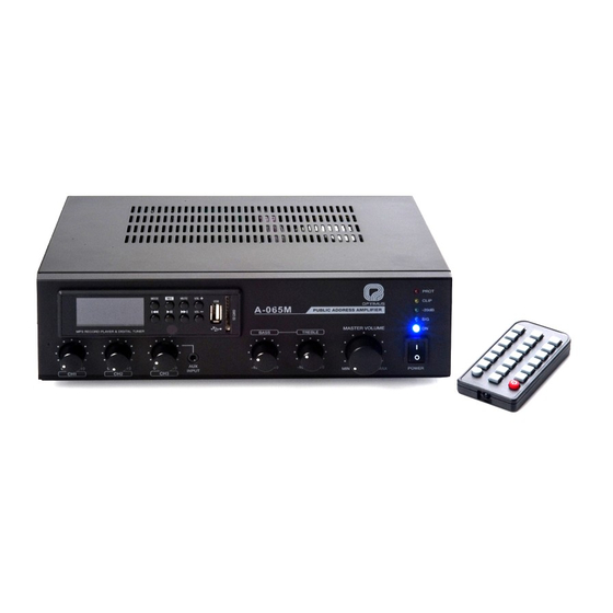
- Page 1 AMPLIFICADOR AMPLIFIER A-065M Manual de instalación y funcionamiento v1.0 Installation and operating instructions v1.0...
- Page 2 Utilizar SIEMPRE un cable doble aislante de calidad equivalente a los de la red de baja tensión para las conexiones de los altavoces. ASEGURARSE de que todos los altavoces estén en fase. ASEGURARSE de que no existe ningún cortocircuito en la línea de altavoces antes de conectarla al amplificador. A-065M Versión 1.0 Página 1 de 13...
-
Page 3: Table Of Contents
DIAGRAMA DE BLOQUES.................9 FUENTE MUSICAL ...................10 ESPECIFICACIONES TÉCNICAS ............11 7.1. Amplificador ......................11 7.2. Fuente musical....................12 CERTIFICADO DE GARANTÍA..............13 A-065M Versión 1.0 Página 2 de 13... -
Page 4: Características
• Instalación en sobremesa o en rack de 19”. • Controles de tono de dos bandas, agudos y graves. • Bajo nivel de ruido y distorsión. • Perfecto para uso comercial e industrial. A-065M Versión 1.0 Página 3 de 13... -
Page 5: Descripción
5. Entradas de audio. XLR (CH1), JACK/RCA (CH2 y CH3 MIC/LINE). 6. Interruptor de alimentación Phantom. 7. Interruptor de activación de prioridad. 8. Entrada TEL-PAGING con controles de volumen y nivel de activación. 9. Conector de antena de radio. A-065M Versión 1.0 Página 4 de 13... -
Page 6: Instalación
3.2. Conexión de entradas La siguiente figura muestra los pines asignados para el cableado. Las conexiones de entrada RCA pueden ser usadas para entradas no balanceadas. A-065M Versión 1.0 Página 5 de 13... -
Page 7: Conexión De Salidas De Altavoces
El equipo incluye dos terminales de baja impedancia 4 Ω and 8 Ω, y tos terminales de alta impedancia 70 V y 100 V. El cableado se muestra en las siguientes figuras. Nunca use distintos terminales simultáneamente. A-065M Versión 1.0 Página 6 de 13... -
Page 8: Funcionamiento
El equipo dispone de tres niveles de prioridad: TEL-PAGING. CH1 (con la prioridad activada) CH1 (sin prioridad activada), CH2 y CH3. 4.3. Alimentación Phantom El equipo dispone de alimentación Phantom +15 Vcc, seleccionable para el canal 1. A-065M Versión 1.0 Página 7 de 13... -
Page 9: Music On Hold
Conecte la salida MOH del amplificador a la entrada MOH del equipo externo/PBX. Ajuste el volumen MOH al nivel deseado. La salida MOH reproducirá el audio de los canales 2 y 3, y el de la fuente musical interna. A-065M Versión 1.0 Página 8 de 13... -
Page 10: Diagrama De Bloques
A-065M Amplificador DIAGRAMA DE BLOQUES A-065M Versión 1.0 Página 9 de 13... -
Page 11: Fuente Musical
11. REC. Activa el modo grabación. 12. Receptor IR. El equipo dispone, en el modo MSC, de un ecualizador con distintos preajustes POP/ROCK/CLASSIC/OFF. Esta función solo puede activarse desde el mando a distancia. A-065M Versión 1.0 Página 10 de 13... -
Page 12: Especificaciones Técnicas
1/8 potencia 24,9 W Sin carga 8,5 W 270 x 76 x 230 mm Dimensiones (Ancho / Alto / Profundo) Peso neto 3,59 kg Accesorios Cable de alimentación 0 dB = 775 mV A-065M Versión 1.0 Página 11 de 13... -
Page 13: Fuente Musical
Respuesta en frecuencia Tensión de alimentación 12 Vcc Peso 0,1 kg Dimensiones (Ancho / Alto / Profundo) 120 x 37 x 24 mm Accesorios Antena FM, mando a distancia 0 dB = 775 mV A-065M Versión 1.0 Página 12 de 13... -
Page 14: Certificado De Garantía
éstas hayan sido ejecutadas debidamente o no. 13. Todas las piezas o productos sustituidos al amparo de los servicios en OPTIMUS S.A. tampoco asumirá costes en el marco de la garantía por este tipo garantía pasarán a ser propiedad de OPTIMUS S.A. - Page 15 ALWAYS use a mains grade double insulated cable for the loudspeaker cable runs. ENSURE that all loudspeakers are in-phase. ENSURE that there are no short circuits on the loudspeaker line before connecting to the amplifier. Page 1 of 13 A-065M Version 1.0...
- Page 16 MUSIC SOURCE ..................10 TECHNICAL SPECIFICATIONS ............... 11 7.1. Amplifier ......................11 7.2. Music source ....................... 12 GUARANTEE CERTIFICATE ..............13 Page 2 of 13 A-065M Version 1.0...
- Page 17 Advanced protection system includes current limiting, over current and thermal protection. • Desktop and 19-inches rack mountable type. • Two bands tone controls. • Low distortion and low noise level. • Ideal for commercial and industrial use. Page 3 of 13 A-065M Version 1.0...
- Page 18 4. Gain controls. 5. Signal input connectors. XLR (CH1), JACK/RCA (CH2 & CH3 MIC/LINE). 6. Phantom ON/OFF switch. 7. Priority switch. 8. Tel-paging input with level and TALKOVER depth controls. 9. FM Antenna connector. Page 4 of 13 A-065M Version 1.0...
- Page 19 In case of rack mounting, do not stack the units directly; leave an empty space between them to ensure a correct convection cooling. 3.2. Input connections The following figures show pin assignments for each cable type. RCA input connectors can be used for unbalanced inputs. Page 5 of 13 A-065M Version 1.0...
- Page 20 The equipment includes two low impedance terminals 4 Ω and 8 Ω, and two high impedance terminals 70 V and 100 V. The wiring is shown in the following pictures. Never use different output terminals at the same time. Page 6 of 13 A-065M Version 1.0...
- Page 21 TEL-PAGING activation threshold can be adjusted by TALKOVER control. This equipment has two priority layers: TEL-PAGING. CH1 (With priority activated) CH1 (Without priority activated), CH2 y CH3. 4.3. Phantom power This equipment has Phantom power +15 Vdc selectable for Channel 1. Page 7 of 13 A-065M Version 1.0...
- Page 22 Connect amplifier’s MOH output to music-on-hold input of telephone interface/PBX. Set MUSIC ON HOLD volume to proper level. Audio of Channels 2 and 3 as well as audio of internal BGM source will be broadcasted by MOH output. Page 8 of 13 A-065M Version 1.0...
- Page 23 A-065M Amplifier BLOCK DIAGRAM Page 9 of 13 A-065M Version 1.0...
- Page 24 10. Automatic or manual tuning down / track select down (FM / MSC). (NEXT in mode selection). 11. REC. Activates Record mode. 12. IR communication receiver. The unit includes, in MSC mode, an equalizer with different presets POP/ROCK/CLASSIC/OFF. This function can only be activated from remote control. Page 10 of 13 A-065M Version 1.0...
- Page 25 Power consumption 1/8 power 24.9 W Unloaded 8.5 W 270 x 76 x 230 mm Dimensions (width / Height / Depth) 3.59 kg Net Weight AC power cable Accessories 0 dB = 775 mV Page 11 of 13 A-065M Version 1.0...
- Page 26 20 ~ 20.000 Hz Frequency response 12 Vdc Supply voltage 0.1 kg Weight 120 x 37 x 24 mm Dimensions (Width / Height / Depth) FM antenna, remote control Accessories 0 dB = 775 mV Page 12 of 13 A-065M Version 1.0...
- Page 27 In the event that the guarantee rights do not 3. No guarantee benefits shall be provided other than those cited here. apply, OPTIMUS S.A. shall duly inform the client. If, within a period of 6 weeks from this communication, no written repair order is received from the client 4.
Need help?
Do you have a question about the A-065M and is the answer not in the manual?
Questions and answers