
Related Manuals for Optimus AM-30


Summary of Contents for Optimus AM-30
- Page 1 AMPLIFICADOR AMPLIFIER AM-30 AM-60 Manual de instalación y funcionamiento v1.0 Installation and operating instructions v1.0...
- Page 2 ASEGURARSE de que todos los altavoces estén en fase. ASEGURARSE de que no existe ningún cortocircuito en la línea de altavoces antes de conectarla al amplificador. AM-30 / AM-60 Versión 1.0 Página 1 de 8...
-
Page 3: Table Of Contents
4.4.1. Línea de 100 V ........................6 4.4.2. Línea de 70 V (Seleccionable desde PCB)..............6 4.4.3. Baja impedancia (4 Ω, 8 Ω, 16 Ω) ..................6 ESPECIFICACIONES TÉCNICAS ....................7 CERTIFICADO DE GARANTÍA ....................8 AM-30 / AM-60 Versión 1.0 Página 2 de 8... -
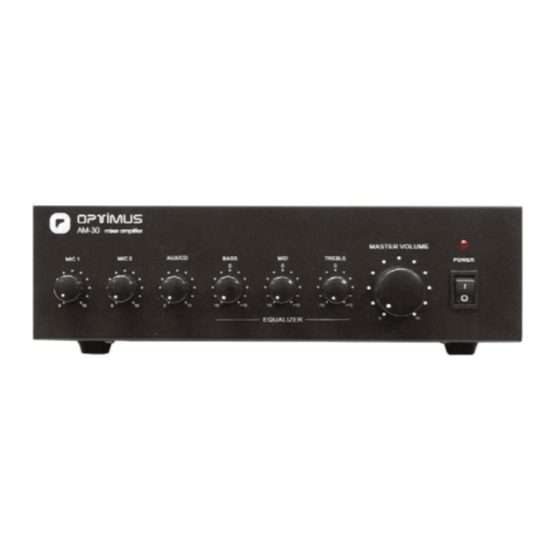
Page 4: Panel Frontal
3. Tornillo de conexión a masa 9. Entrada MIC 2 (Jack Mono 1/4”) 4. Terminales de prioridad manual 10. Entrada MIC 1 (DIN / Balanceado) 5. Terminales de salida a altavoces AM-30 / AM-60 Versión 1.0 Página 3 de 8... -
Page 5: Diagrama De Bloques
AM-30 / AM-60 Amplificador 3. DIAGRAMA DE BLOQUES AM-30 / AM-60 Versión 1.0 Página 4 de 8... -
Page 6: Conexiones
Cuerpo: GND Punta: Señal AM-30 / AM-60 Versión 1.0 Página 5 de 8... -
Page 7: Terminales De Prioridad Manual
4 Ω. Cuando se conecte más de un altavoz, asegúrese que estén cableados de tal forma que la impedancia total tenga un valor entre 4 Ω y 16 Ω. AM-30 / AM-60 Versión 1.0 Página 6 de 8... -
Page 8: Especificaciones Técnicas
> 60 dB SNR entradas AUX/CD > 70 dB Ecualizador 150Hz, 1KHz, 6KHz ± 10 dB Dimensiones (alto x ancho x fondo) 90 x 270 x 260 mm Peso 4,25 kg 5,0 kg AM-30 / AM-60 Versión 1.0 Página 7 de 8... -
Page 9: Certificado De Garantía
éstas hayan sido ejecutadas debidamente o no. los gastos de flete y seguro. OPTIMUS S.A. tampoco asumirá costes en el marco de la garantía por este tipo 12. En caso de falla, OPTIMUS S.A. asegura al comprador la reparación y/o de modificaciones. - Page 10 ALWAYS use a mains grade double insulated cable for the loudspeaker cable runs. ENSURE that all loudspeakers are in-phase. ENSURE that there are no short circuits on the loudspeaker line before connecting to the amplifier. Page 1 of 8 AM-30 / AM-60 Version 1.0...
- Page 11 100 V line ........................... 6 4.4.2. 70 V line (inner PCB selectable)..................6 4.4.3. Low impedance (4 Ω, 8 Ω, 16 Ω)..................6 ..................7 TECHNICAL SPECIFICATIONS ................... 8 GUARANTEE CERTIFICATE Page 2 of 8 AM-30 / AM-60 Version 1.0...
- Page 12 3. Ground connection screw 8. Selector switch AUX / CD 4. Manual priority contacts 9. MIC 2 input (Jack Mono 1/4”) 5. Loudspeakers output connectors 10. MIC 1 input (DIN / Balanced) Page 3 of 8 AM-30 / AM-60 Version 1.0...
- Page 13 AM-30 / AM-60 Amplifier 3. BLOCK DIAGRAM Page 4 of 8 AM-30 / AM-60 Version 1.0...
- Page 14 Ring: GND Tip: Signal Page 5 of 8 AM-30 / AM-60 Version 1.0...
- Page 15 This output allows connection of standard low impedance loudspeakers, the minimum load impedance is 4 Ω. When two or more loudspeakers are used ensure that they are wired in such a way that load impedance remains between 4 Ω and 16 Ω. Page 6 of 8 AM-30 / AM-60 Version 1.0...
- Page 16 > 60 dB AUX/CD input SNR > 70 dB Equalizer 150Hz, 1KHz, 6KHz ± 10 dB Dimensions (H x W x D) mm 90 x 270 x 260 Weight 4,25 kg 5,0 kg Page 7 of 8 AM-30 / AM-60 Version 1.0...
- Page 17 In the event that the guarantee rights do not replacement parts are applied which improve the unit, OPTIMUS S.A. reserves apply, OPTIMUS S.A. shall duly inform the client. If, within a period of 6 weeks the right to charge the client for the additional cost of these components.
Need help?
Do you have a question about the AM-30 and is the answer not in the manual?
Questions and answers