
Related Manuals for Optimus AXF-240


Summary of Contents for Optimus AXF-240
- Page 1 AXF-240 AMPLIFICADOR AMPLIFIER Manual de instalación y funcionamiento v1.0 Installation and operating instructions v1.0...
- Page 2 AXF-240 AMPLIFICADOR INSTRUCCIONES DE SEGURIDAD: IMPORTANTE: Los códigos de color de los cables de red son los siguientes: Verde y amarillo Tierra Azul Neutro Marrón Positivo Si los colores de los cables de red de este aparato no se corresponden con las marcas de sus terminales de conexión, debe procederse como sigue: Conectar el cable de color verde y amarillo al terminal marcado con la letra E o con el símbolo de tierra.
-
Page 3: Table Of Contents
AXF-240 AMPLIFICADOR ÍNDICE DESCRIPCIÓN ........................3 CARACTERÍSTICAS ......................... 3 PANEL FRONTAL ........................4 PANEL POSTERIOR ........................ 5 CONEXIÓN ..........................6 5.1. CONEXIÓN A LA RED ELÉCTRICA ..................6 5.2. PUENTE CHASIS MASA ....................6 5.3. ENTRADAS DE MICRÓFONO MIC 1, 2, 3, 4 Y 5 ............... 7 5.4. -
Page 4: Descripción
AXF-240 AMPLIFICADOR 1. DESCRIPCIÓN Amplificador de 240 W con fuente musical, 5 entradas de micro, 2 auxiliares y una de emergencia. Dispone de protección contra sobretensión, cortocircuito, sobrecarga y alta temperatura. También tiene indicadores LED de potencia, señal, pico y protección. -
Page 5: Panel Frontal
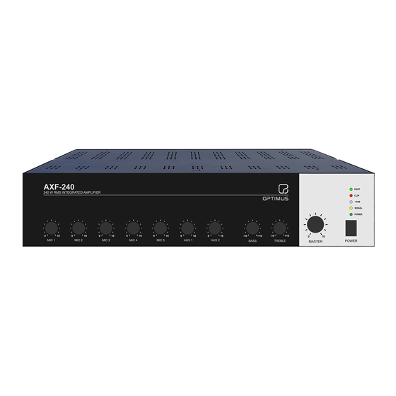
AXF-240 AMPLIFICADOR 3. PANEL FRONTAL 1. Indicador LED PROT. Se ilumina en rojo si el amplificador entra en estado de protección. 2. Indicador LED CLIP. Se ilumina en amarillo cuando el nivel de salida es demasiado alto. 3. Indicador LED -10 dB. -
Page 6: Panel Posterior
AXF-240 AMPLIFICADOR 4. PANEL POSTERIOR 1. Puente chasis masa. 2. Entrada de alimentación CA. Entrada de alimentación de 115 a 230 Vca (50/60 Hz). El voltaje es autoajustable. 3. Compartimiento para fusible. 4. Salida de altavoces. Salida de altavoces de 100V, 70V y 4 Ω. -
Page 7: Conexión
AXF-240 AMPLIFICADOR 5. CONEXIÓN 5.1. CONEXIÓN A LA RED ELÉCTRICA Asegúrese de que la tensión de red coincide con los requisitos del amplificador. Use el cable de alimentación del equipo para conectarlo a la red eléctrica. El equipo viene configurado de fábrica para ser alimentado de 115 a 230 Vca (50/60 Hz). La adaptación de tensión es automática. -
Page 8: Entradas De Micrófono Mic 1, 2, 3, 4 Y 5
AXF-240 AMPLIFICADOR 5.3. ENTRADAS DE MICRÓFONO MIC 1, 2, 3, 4 Y 5 Entradas de audio balanceadas a través de conector XLR y con una sensibilidad de entrada de -50 dB y 600 Ω. Es posible cambiar la sensibilidad mediante jumpers internos. -
Page 9: Entradas Aux 1 Y Aux 2
AXF-240 AMPLIFICADOR 5.4. ENTRADAS AUX 1 y AUX 2 Entradas de audio no balanceadas a través de conector RCA. Disponen de sensibilidad ajustable de -30 dB a +14 dB mediante el potenciómetro correspondiente. 5.5. ENTRADA EMG INPUT Entrada de audio balanceada a través de conector XLR con una sensibilidad de entrada de 0 dB a 10 kΩ. -
Page 10: Salida Line Out
AXF-240 AMPLIFICADOR 5.6. SALIDA LINE OUT La unidad incluye una salida de línea de audio balanceada mediante conexión XLR. Esta salida transmite el audio de todo el sistema, entradas generales y prioritarias, y no se ve afectada por el control de volumen Master ni los controles de tono. -
Page 11: Prioridad
AXF-240 AMPLIFICADOR 5.8. PRIORIDAD El equipo dispone de diferentes niveles de prioridad. Prioridad 1 (máx.): Entrada EMG (Pri. Por contacto o VOX) Prioridad 2: MIC 1(Pri) = MIC 2(Pri) = MIC 3(Pri) = MIC 4(Pri) = MIC 5(Pri) (Pri. Por contacto o VOX) Prioridad 3: AUX 1 = AUX 2 = MIC 1 = MIC 2 = MIC 3 = MIC 4 = MIC 5. -
Page 12: Baja Impedancia 4 Ω
AXF-240 AMPLIFICADOR 5.9.2. BAJA IMPEDANCIA 4 Ω Conecte los altavoces en serie o paralelo. La impedancia total de la línea de altavoces debe ser 4 Ω, y la suma de potencia soportada por los altavoces debe ser mayor 240 W. -
Page 13: Relé Surety Paging
AXF-240 AMPLIFICADOR 5.10. RELÉ SURETY PAGING Este relé conmuta cuando se activa la prioridad de cualquiera de las entradas y se utiliza para activar elementos externos. Por ejemplo, permite la activación de la preferencia de la palabra en las atenuadoras de audio. -
Page 14: Configurar La Sensibilidad De Las Entradas
AXF-240 AMPLIFICADOR 5.11. CONFIGURAR LA SENSIBILIDAD DE LAS ENTRADAS Es posible cambiar la sensibilidad de entrada de los micrófonos MIC 1, 2, 3, 4 y 5, de nivel de Micro (por defecto) a nivel de Auxiliar. Este cambio se tiene que hacer internamente mediante los siguientes Jumpers. -
Page 15: Configurar Control Por Vox
AXF-240 AMPLIFICADOR 5.12. CONFIGURAR CONTROL POR VOX Es posible activar el VOX en las entradas de micrófono (MIC1, 2, 3, 4 y 5) y en la de emergencia (EMC). Este cambio se tiene que hacer internamente mediante los siguientes Jumpers. -
Page 16: Especificaciones
AXF-240 AMPLIFICADOR 6. ESPECIFICACIONES Modelo AXF-240 Potencia Nominal de Salida 240 W 100 V, 70 V y 4 Ω Salidas Preout & Amp in: 0 dB (20 kΩ no balanceado) Line out: 0 dB (10 kΩ balanceado) Contacto de salida Relé... -
Page 17: Certificado De Garantía
7. CERTIFICADO DE GARANTÍA 1. CERTIFICADO DE GARANTÍA 1. La empresa OPTIMUS S.A. garantiza que sus productos se encuentran libres de defectos en materiales y de mano de obra en el momento de su entrega original al comprador. 2. La empresa OPTIMUS S.A. concede a sus productos, conforme a las condiciones aquí descritas, una garantía de dos (2) años a partir de la fecha de adquisición del producto por el comprador. - Page 18 AXF-240 AMPLIFIER SAFETY INSTRUCTIONS: IMPORTANT: The wires in the mains lead are coloured in accordance with the following code: Green and Yellow Earth Blue Neutral Brown Live If the colours of the wires in the mains lead of this apparatus do not correspond with the colour markings identifying the...
- Page 19 AXF-240 AMPLIFIER INDEX DESCRIPTION ........................3 FEATURES ..........................3 FRONTAL PANEL ........................4 REAR PANEL .......................... 5 CONNECTION ........................6 5.1. AC MAINS CONNECTION ....................6 5.2. FRAME TO GND LINK ..................... 6 5.3. MIC 1, 2, 3, 4 Y 5 INPUTS ....................7 5.4.
- Page 20 AXF-240 AMPLIFIER 1. DESCRIPTION 240 W amplifier with five (5) microphone inputs, two (2) auxiliar inputs and one (1) emergency input. Clip, short circuit, overload and high temperature protection are available. It also has LED indicators for power, signal, peak and protection.
- Page 21 AXF-240 AMPLIFIER 3. FRONTAL PANEL 1. LED PROT indicator. It lights in red once the amplifier comes into protection status. 2. LED CLIP indicator. It lights yellow when the output level is too high. 3. LED -10 dB indicator. It lights green when the output audio level reaches -10 dB.
- Page 22 AXF-240 AMPLIFIER 4. REAR PANEL 1. Frame to GND link. 2. AC Power socket. Power input from 115 to 230 Vac (50/60 Hz). The voltage is self-adjusting. 3. Fuse holder. 4. Speaker outputs. 100V, 70V and 4 Ω speaker output.
- Page 23 AXF-240 AMPLIFIER 5. CONNECTION 5.1. AC MAINS CONNECTION Please, make sure that AC mains match with equipment voltage specifications. Use the equipment power cord to connect it to AC mains. The unit is factory set to be supplied from 115 to 230 Vac 50/60 Hz. Voltage switching is automatic.
- Page 24 AXF-240 AMPLIFIER 5.3. MIC 1, 2, 3, 4 Y 5 INPUTS Balanced audio inputs through XLR connector and input sensitivity of -50 dB 600 Ω. It is possible to change the sensitivity through internal jumpers. To activate input priority, it is necessary to close the two PRIORITY INPUT terminals (link the two terminals).
- Page 25 AXF-240 AMPLIFIER 5.4. AUX 1 AND AUX 2 INPUTS Unbalanced audio inputs through XLR connector. Adjustable sensitivity from -30 dB to +14 dB using the corresponding potentiometer. 5.5. EMERGENCY (EMG) INPUT Balanced audio input through XLR connector. Input sensitivity of 0 dB at 10 kΩ.
- Page 26 AXF-240 AMPLIFIER 5.6. LINE OUT The unit includes a balanced audio line output though XLR connection. This output broadcasts the audio of the whole system, general and priority inputs, and it is not affected by Master, Bass and Treble volume controls.
- Page 27 AXF-240 AMPLIFIER 5.8. PRIORITY The equipment has different levels of priority. Priority 1 (max.): EMG input (Contact or VOX activation) Priority 2: MIC 1(Pri) = MIC 2(Pri) = MIC 3(Pri) = MIC 4(Pri) = MIC 5(Pri) (Contact or VOX activation) Priority 3: AUX 1 = AUX 2 = MIC 1 = MIC 2 = MIC 3 = MIC 4 = MIC 5 5.9.
- Page 28 AXF-240 AMPLIFIER 5.9.2. 4 Ω LOW IMPEDANCE Connect the speakers in series or parallel. The total impedance of the speaker line must be 4 Ω, and the sum of power supported by the speakers must be greater than 240 W.
- Page 29 AXF-240 AMPLIFIER 5.10. RELÉ SURETY PAGING This relay switches when the priority of any of the inputs is activated and it is used to activate external elements. The follow example shows the connection diagram in order to provide security paging with 3 wire attenuators.
- Page 30 AXF-240 AMPLIFIER 5.11. INPUTS SENSITIVITY CONFIGURATION It is possible to change the input sensitivity of microphones MIC 1, 2, 3, 4, 5, from Mic level (default) to Aux level. This change has to be done internally through the following Jumpers.
- Page 31 AXF-240 AMPLIFIER 5.12. VOX CONTROL CONFIGURATION It is possible to activate VOX on the microphone inputs (MIC1, 2, 3, 4 and 5) and the emergency input (EMC). This change has to be done internally through the following Jumpers. CH5 (MIC5) connection example.
- Page 32 AXF-240 AMPLIFIER 6. SPECIFICATIONS Model AXF-240 Rated Power Output 240 W 100 V, 70 V and 4 Ω Outputs Preout & Amp in: 0dB (20 kΩ unbalanced) Line out: 0 dB (10 k Ω balanced) Contact output Surety Paging Relay (8 A 250 Vac) Mic1-5: -50 dB (600 Ω...
- Page 33 12. In the event of a defect, OPTIMUS S.A. guarantees that the repair and/or replacement of parts so that the unit operates correctly will be made within a period of no more than 30 days. Nevertheless, OPTIMUS S.A. would like to clarify that the normal period does not exceed 30 days.
- Page 34 C/ Barcelona 101 17003 Girona (Spain) (+34) 972 203 300 20230519 www.optimusaudio.com...
Need help?
Do you have a question about the AXF-240 and is the answer not in the manual?
Questions and answers