
Related Manuals for Optimus A-240MZ


Summary of Contents for Optimus A-240MZ
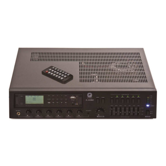
- Page 1 AMPLIFICADOR AMPLIFIER A-240MZ Manual de instalación y funcionamiento v1.1 Installation and operating instructions v1.1...
- Page 2 Utilizar SIEMPRE un cable doble aislante de calidad equivalente a los de la red de baja tensión para las conexiones de los altavoces. ASEGURARSE de que todos los altavoces estén en fase. ASEGURARSE de que no existe ningún cortocircuito en la línea de altavoces antes de conectarla al amplificador. A-240MZ Versión 1.1 Página 1 de 16...
-
Page 3: Table Of Contents
ESPECIFICACIONES TÉCNICAS ............14 8.1. Amplificador ......................14 8.2. Fuente musical ....................15 8.3. PM-5Z ......................... 15 CERTIFICADO DE GARANTÍA ..............16 A-240MZ Versión 1.1 Página 2 de 16... -
Page 4: Características
Instalación en sobremesa o en rack de 19”. Ecualizador gráfico de siete bandas. Ampliable mediante los conectores LINK y PRE-AMP. Bajo nivel de ruido y distorsión. Perfecto para uso comercial e industrial. A-240MZ Versión 1.1 Página 3 de 16... -
Page 5: Descripción
22. Terminales para líneas de altavoces de 17. Interruptores de alimentación Phantom y alta impedancia. control de prioridad. 23. Fusible. 18. Entradas de audio para canales 1-6. 24. Toma de corriente alterna. 25. Control de Mute externo. A-240MZ Versión 1.1 Página 4 de 16... -
Page 6: Instalación
3. Inserte los tornillos en los agujeros de la escuadra y el chasis. Atorníllelos. 4. Repita los dos pasos anteriores para el otro lateral del chasis. 5. Retire las cuatro patas de la parte inferior de la unidad. Para mayor detalle, observe la siguiente figura. A-240MZ Versión 1.1 Página 5 de 16... -
Page 7: Conexión De Entradas
A-240MZ Amplificador 3.4. Conexión de entradas La siguiente figura muestra los pines asignados para el cableado. Las conexiones de entrada RCA pueden ser usadas para entradas no balanceadas. A-240MZ Versión 1.1 Página 6 de 16... -
Page 8: Conexión De Salidas De Altavoces
Seleccione el tamaño del cable adecuado en función de la distancia entre el amplificador y los altavoces. Para modificar la tensión de salida de las líneas de alta impedancia debe cambiarse la siguiente conexión interna. TERMINAL 100 V PIN 19 ROJO AZUL PIN 23 AZUL ROJO A-240MZ Versión 1.1 Página 7 de 16... -
Page 9: Conexión De Equipos Externos
. El audio de la salida LINK OUT no se ve afectado por el control de volumen master. A-240MZ Versión 1.1 Página 8 de 16... -
Page 10: Funcionamiento
2 CH1- CH2 (sin prioridad activada) y CH3 - CH6. El audio prioritario proveniente de los canales de micrófono 1 y 2, y de la entrada TELE-PAGING, solo se emitirá por las salidas habilitadas previamente desde el frontal. A-240MZ Versión 1.1 Página 9 de 16... -
Page 11: Alimentación Phantom
MOH al nivel deseado. Ajuste el selector de entrada en la posición INT para enviar el audio de la fuente interna (CD/MP3) o en EXT para enviar el audio de la entrada EXT MOH (CH6). A-240MZ Versión 1.1 Página 10 de 16... -
Page 12: Diagrama De Bloques
A-240MZ Amplificador DIAGRAMA DE BLOQUES A-240MZ PM-5Z A-240MZ Versión 1.1 Página 11 de 16... -
Page 13: Microfono Remoto Pm-5Z
REMOTE MIC en la parte posterior del amplificador. Lock-Unlock: Utilice este conmutador para fijar las zonas seleccionadas. Con el conmutador en posición “unlock” marque las zonas deseadas, mueva el interruptor a la posición “lock” y quedarán permanente activadas. A-240MZ Versión 1.1 Página 12 de 16... -
Page 14: Fuente Musical
18. Decrementa la frecuencia de la emisora en modo FM o la pista en modo MSC. (Siguiente en selección de modo). 19. Carpeta siguiente en modo BGM o emisora siguiente en modo FM. 20. REC. Activa el modo grabación. 21. Receptor IR. A-240MZ Versión 1.1 Página 13 de 16... -
Page 15: Especificaciones Técnicas
Sin carga 24,9 W 420 x 88 x 320 mm Dimensiones (Ancho / Alto / Profundo) 7,3 kg Peso neto Escuadras de montaje en rack Accesorios Cable de alimentación 0 dB = 775 mV A-240MZ Versión 1.1 Página 14 de 16... -
Page 16: Fuente Musical
Relación señal ruido 0 dB / 600 Ω Nivel de salida / Impedancia 0º~40ºC (95% humedad) Temperatura de funcionamiento 0,9 kg Peso 140 x 60 x 205 mm Dimensiones (Ancho / Alto / Profundo) A-240MZ Versión 1.1 Página 15 de 16... -
Page 17: Certificado De Garantía
éstas hayan sido ejecutadas debidamente o no. 13. Todas las piezas o productos sustituidos al amparo de los servicios en OPTIMUS S.A. tampoco asumirá costes en el marco de la garantía por este tipo garantía pasarán a ser propiedad de OPTIMUS S.A. - Page 18 ALWAYS use a mains grade double insulated cable for the loudspeaker cable runs. ENSURE that all loudspeakers are in-phase. ENSURE that there are no short circuits on the loudspeaker line before connecting to the amplifier. Page 1 of 16 A-240MZ Version 1.1...
- Page 19 TECHNICAL SPECIFICATIONS ............... 14 8.1. Amplifier ......................14 8.2. Music source ....................... 15 8.3. PM-5Z ......................... 15 GUARANTEE CERTIFICATE ..............16 Page 2 of 16 A-240MZ Version 1.1...
- Page 20 Desktop and 19-inches rack mountable type. Seven band graphic equalizer. Expandable by using LINK and PRE-AMP terminals. Low distortion and low noise level. Ideal for commercial and industrial use. Page 3 of 16 A-240MZ Version 1.1...
- Page 21 15. Tel-Paging input and volume control. 23. Fuse. 16. Gain controls for channels 1-6. 24. AC power inlet. 17. Phantom and priority switches. 25. External mute control. 18. Signal input connectors for channels 1-6. Page 4 of 16 A-240MZ Version 1.1...
- Page 22 3. Insert the screws into the holes of the rack-ear and frame. Screw them in. 4. Repeat steps for the left side of the frame. 5. Remove the four legs from bottom of unit. Please refer to the following figure. Page 5 of 16 A-240MZ Version 1.1...
- Page 23 A-240MZ Amplifier 3.4. Input connections The following figures show pin assignments for each cable type. RCA input connectors can be used for unbalanced inputs. Page 6 of 16 A-240MZ Version 1.1...
- Page 24 Select the appropriate wire size based on the distance between amplifier and speakers. In order to change the output voltage of High impedance terminals the following internal connection has to be done. TERMINAL 100 V PIN 19 BLUE PIN 23 BLUE Page 7 of 16 A-240MZ Version 1.1...
- Page 25 This amplifier allows expansion with LINK IN and LINK OUT connectors. If you need more inputs and outputs, you can use these connectors to link the amplifier to another unit. Audio from LINK-OUT is not affected by master volume control. Page 8 of 16 A-240MZ Version 1.1...
- Page 26 2 CH1 – CH2 (without priority activated) and CH3 - CH6. Priority audio from channels 1 and 2, and TELE-PAGIN input, will only be broadcasted by the zones previously selected in the front panel. Page 9 of 16 A-240MZ Version 1.1...
- Page 27 HOLD volume to proper level. When MUSIC ON HOLD slide switch is set to “INT” position, MUSIC ON HOLD output is routed from internal module (CD/MP3). When the slide switch is set to “EXT” position, MUSIC ON HOLD output is routed from LINE IN channel (CH6). Page 10 of 16 A-240MZ Version 1.1...
- Page 28 A-240MZ Amplifier BLOCK DIAGRAM A-240MZ PM-5Z Page 11 of 16 A-240MZ Version 1.1...
- Page 29 Chime volume only, use the volume control placed next to REMOTE MIC input in the amplifier rear panel. Lock-Unlock: Use this switch to lock selected zones. To lock the zones, select desired ones and then set the switch to “Lock” position. Page 12 of 16 A-240MZ Version 1.1...
- Page 30 18. Automatic or manual tuning down / track search down (FM / MSC). (NEXT in mode selection). 19. Search up folder for MSC or preset frequency for FM. 20. REC. Activates Record mode. 21. IR communication receiver. Page 13 of 16 A-240MZ Version 1.1...
- Page 31 1/8 power 65,5 W Unloaded 24.9 W 420 x 88 x 320 mm Dimensions (width / Height / Depth) 7.3 kg Net Weight Rack mounting brackets, AC power cable Accessories 0 dB = 775 mV Page 14 of 16 A-240MZ Version 1.1...
- Page 32 > 90 dB S/N ratio 0 dB / 600 Ω Rated output level / impedance 0º~40ºC (95% humidity) Operating Temperature 0.9 kg Weight 140 x 60 x 205 mm Dimensions (Width / Height / Depth) Page 15 of 16 A-240MZ Version 1.1...
- Page 33 In the event that the guarantee rights do not 3. No guarantee benefits shall be provided other than those cited here. apply, OPTIMUS S.A. shall duly inform the client. If, within a period of 6 weeks from this communication, no written repair order is received from the client 4.
Need help?
Do you have a question about the A-240MZ and is the answer not in the manual?
Questions and answers