
Related Manuals for Optimus UP-367


Summary of Contents for Optimus UP-367
- Page 1 Español Español English English UP-67 UP-127 UP-247 UP-367 AMPLIFICADOR AMPLIFIER Manual de instrucciones N º . Operating instructions...
-
Page 3: Table Of Contents
8. CERTIFICADO DE GARANTÍA ............12 UP-367, UP-247, UP-127 y UP-67 Versión 1.0... -
Page 4: Introducción
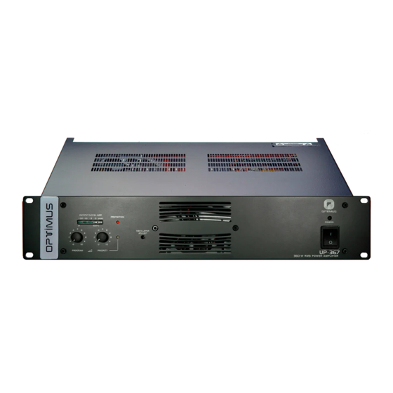
AMPLIFICADORES UP-367, UP-247, UP-127 y UP-67 1. INTRODUCCIÓN Los modelos UP-367, UP-247, UP-127 y UP-67 son amplificadores de 360, 240, 120 y 60 Wats R.M.S. respectivamente. Indicados para ser utilizados en instalaciones de megafonía, avisos de emergencia, música ambiental y reproducción de la palabra, destacan por su robustez y fiabilidad. -
Page 5: Vista Posterior
Si las masas están también unidas por los circuitos de señal, es aconsejable quitar el puente entre la masa y el chasis de todos los aparatos excepto uno. RELÉ FAIL Se activa cuando actúa la protección o falla la alimentación de red del amplificador. CONTACTO DE MASA CONTACTO DE CHASIS UP-367, UP-247, UP-127 y UP-67 Versión 1.0... - Page 6 E S PA Ñ O L AMPLIFICADORES UP-367, UP-247, UP-127 y UP-67 SALIDA LÍNEA DE ALTAVOCES Figura 3 La salida de la línea de altavoces se efectúa a través de un transformador que dispone de salidas en baja impedancia (4 - 8 - 16 Ohms) y en alta...
- Page 7 PROGRAM CHANNEL CONNECTION INPUT TRANSFORMER Pin number 1: SIGNAL H T-700 Pin number 2: SIGNAL C (if the input is balanced) Pin number 3: +24VDC Pin number 8: 600 Ohm 600 Ohm N.C. N.C. Shield UP-367, UP-247, UP-127 y UP-67 Versión 1.0...
- Page 8 E S PA Ñ O L AMPLIFICADORES UP-367, UP-247, UP-127 y UP-67 DIPSWITCH DE CONFIGURACIÓN OPTIMUS S.A. I N P U T / O U T P U T C O N T A C T S PRIORITY PRIORITY U P - 2 4 7...
-
Page 9: El Sistema De Ventilación
Si la temperatura interna del aparato superase los 110ºC se activaría la protección del aparato. Para sustituir los ventiladores en caso de avería, siga las figuras 10 y Figura 11 UP-367, UP-247, UP-127 y UP-67 Versión 1.0... -
Page 10: Diagrama De Bloques
E S PA Ñ O L AMPLIFICADORES UP-367, UP-247, UP-127 y UP-67 5. DIAGRAMA DE BLOQUES PROGRAM INPUT MASTER PROGRAM PROGRAM OUTPUT PRI-PRO LINK PRIORITY OUTPUT PROGRAM POWER PROTECTION 100V STAGE PRIORITY INPUT SPEAKERS PRIORITY LINE 16Ω OUTPUT 8Ω 4Ω... -
Page 11: Características Técnicas
10 kg 13,6 kg 15,7 kg Placa frontal en hierro pintada negra. Tapa en hierro pintada negra. Acabados (*) En condiciones normales el equipo está dimensionado para no necesitar la activación del ventilador. UP-367, UP-247, UP-127 y UP-67 Versión 1.0... -
Page 12: Certificado De Garantía
En caso de ausencia de derechos de garantía, coste adicional de estos componentes al cliente. OPTIMUS S.A. informará al cliente al respecto. Si, en un plazo de 6 semanas a partir de esta comunicación, no recibimos ninguna orden de reparación escrita 3. -
Page 13: List Of Contents
8. GUARANTEE............... . . 22 UP-367, UP-247, UP-127 and UP-67 Version 1.0... -
Page 14: Introduction
AMPLIFIERS UP-367, UP-247, UP-127 and UP-67 1. INTRODUCTION Models UP-367, UP-247, UP-127 and UP-67 are amplifiers with an output of 360, 240, 120 and 60 Wats R.M.S. respectyvely. Suitable for use with public address systems, emergency announcements, background music and reproduction of speech, they are remarkably strong and reliable. -
Page 15: Rearview
FAIL RELAY It is activated when the protection of the amplifier fails or when the power suplí of the amplifier is off. GROUND CONTACT CHASIS CONTACT UP-367, UP-247, UP-127 and UP-67 Version 1.0... - Page 16 E N G L I S H AMPLIFIERS UP-367, UP-247, UP-127 and UP-67 LOUDSPEAKERS LINE OUT The loudspeakers line out is effected by means of a transformer that has Figure 3 low impedance outputs (4 – 8 – 16 Ohms) and high impedance outputs (50 –...
- Page 17 PROGRAM CHANNEL CONNECTION INPUT TRANSFORMER Pin number 1: SIGNAL H T-700 Pin number 2: SIGNAL C (if the input is balanced) Pin number 3: +24VDC Pin number 8: 600 Ohm 600 Ohm N.C. N.C. Shield UP-367, UP-247, UP-127 and UP-67 Version 1.0...
- Page 18 E N G L I S H AMPLIFIERS UP-367, UP-247, UP-127 and UP-67 DIPSWITCH OPTIMUS S.A. I N P U T / O U T P U T C O N T A C T S PRIORITY PRIORITY U P - 2 4 7...
-
Page 19: Ventilantion System
110 ºC, the protection device of the unit itself would be activated. To replace the rear and/or front fan follow the indications in figures 10 and 11. Figure 11 UP-367, UP-247, UP-127 and UP-67 Version 1.0... -
Page 20: Block Diagram
E N G L I S H AMPLIFIERS UP-367, UP-247, UP-127 and UP-67 5. BLOCK DIAGRAM PROGRAM INPUT MASTER PROGRAM PROGRAM OUTPUT PRI-PRO LINK PRIORITY OUTPUT PROGRAM POWER PROTECTION 100V STAGE PRIORITY INPUT SPEAKERS PRIORITY LINE 16Ω OUTPUT 8Ω 4Ω... -
Page 21: Technical Specifications
13.6 kg 15.7 kg Iron front panel black painted. Iron cover black painted Finishes (*) With respect to its size, the unit has been designed not to require the ventilator except in extreme conditions. UP-367, UP-247, UP-127 and UP-67 Version 1.0... -
Page 22: Guarantee
In the event that the guarantee rights do not 4. In order to claim the guarantee rights, it shall be an essential requirement to apply, OPTIMUS S.A. shall duly inform the client. If, within a period of 6 weeks present the original purchase invoice or the guarantee certificate. - Page 24 E-17003 GIRONA (SPAIN) Tel. 902 151 963 Tel. +34 972 203 300 Barcelona, 101 Fax +34 972 218 413 Tel. 972 203 300 E-mail: export@optimus.es Gestión de Proyectos Fax 972 218 413 Tel. 972 222 109 E-mail: girona@optimus.es Fax 972 221 767 E-mail: gproyectos@optimus.es...
Need help?
Do you have a question about the UP-367 and is the answer not in the manual?
Questions and answers