Table of Contents
Advertisement
Quick Links
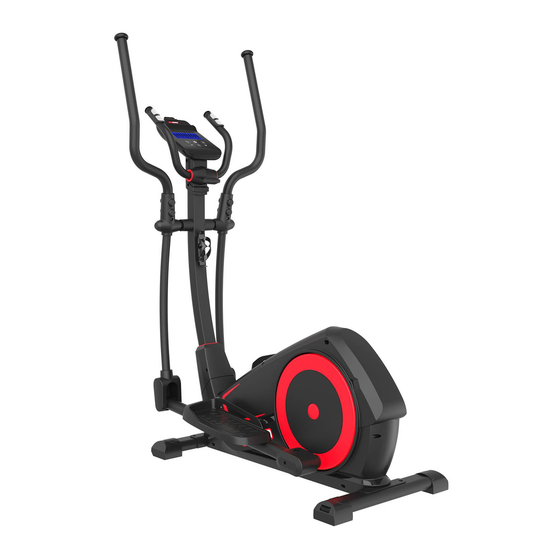
XT2000 Cross Trainer
Assembly & User Instructions-
869/3653
Please Keep for future reference
Important –
Please read these instructions fully before assembly or use
These instructions contain important information which will help you get best from your
equipment and ensure safe and correct assembly, use and maintenance.
If you need help or have damaged or missing parts, call the Customer Helpline: 0345 600 1714
or visit www.argos-support.co.uk
Advertisement
Table of Contents

Related Manuals for Pro Fitness XT2000


Summary of Contents for Pro Fitness XT2000
- Page 1 XT2000 Cross Trainer Assembly & User Instructions- 869/3653 Please Keep for future reference Important – Please read these instructions fully before assembly or use These instructions contain important information which will help you get best from your equipment and ensure safe and correct assembly, use and maintenance.
-
Page 2: Table Of Contents
Contents Safety Information Components - Parts Components – Fixings Assembly Instructions 6-13 Workout Area Exercise Information 15-27 . Before Starting . Muscle Chart . Warning up and Cooling Down 17-18 . Console operation 19-27 Care and Maintenance Exploded Parts Diagram Parts List 30-31... -
Page 3: Safety Information
Safety Information 、 Important – Please read fully before assembly or use This exercise equipment is built for optimum safety. However, certain precautions apply whenever you operate a piece of exercise equipment. Be sure to read the entire manual before you assemble, operate or use this equipment. - Page 4 Safety Information Important – Please read fully before assembly or use • This product conforms to: BS EN ISO 20957-1 and - • When choosing a location for the equipment make 9 Class (H) - Home Use - Class (C). sure that the location and position permit access to a plug.
-
Page 5: Components - Parts
If you have damaged or missing parts, please call the Components - Parts 0345 600 1714 Customer Helpline: http://www.argos-support.co.uk Please check you have all parts listed below Note: Some of the smaller components may be pre-fitted to larger components. Please check carefully before contacting Argos regarding any missing components. -
Page 6: Components - Fixings
Components – Fixings Please check you have all the fixings listed below Note: The quantities below are the correct amount to complete the assembly. In some cases more hardware may be supplied than are required. Some of the fixings are pre-fitted to the larger components. Please check carefully before contacting Argos regarding any missing fixings. -
Page 7: Assembly Instructions
Assembly Instructions Total mass of the product is 43 kg. Total size of the equipment is (width) 67.5 cm × (depth) 122.5 cm × (height) 160.5 cm. Main Frame 32 Left Pedal Left Footplate Bar 33 Right Pedal Right Footplate Bar 34 Handrail Axle Sleeve Front Stabilizer 35 Handrail Front Cover... - Page 8 Assembly Instructions Step 1 a. Attach the Front Stabilizer (4) to the Main Frame (1) using 2 x M10x20mm Allen Bolts (80), 2 x 10mm Washers (74) and 2x10mm Spring Washers (71). b. Attach the Rear Stabilizer (5) to the Main Frame (1) using 2 x M10x20mm Allen Bolts (80), 2 x 10mm Washers (74) and 2x10mm Spring Washers (71).
- Page 9 Assembly Instructions Step 2 a. Attach the Left Footplate (32) to the Left Footplate Bar (2) using 3 x M8×15mm Allen Bolts (79), 3 x Ø8mm Spring Washers (73) and 3 x Ø8mm Washers (75). b. Attach the Right Footplate (33) to the Right Footplate Bar (3) using 3 x M8×15mm Allen Bolts(79), 3 x Ø8mm Spring Washers (73) and 3 x Ø8mm Washers (75).
- Page 10 Assembly Instructions Step 3 a. Connect the Wire (C) to the wire (C1). b. Fix the Front Post (11) to the Main Frame (1) using 6 x M8×15mm Allen Bolts (79), 6 x Ø8mm Spring Washers (73), 2 x Ø9xØ22×R30mm Arc Washers (85) and 4 x Ø8mm Washers (75).
- Page 11 Assembly Instructions Step 4 a. Fix the Left Footplate Bar (2) to the Left Action Arm (12) using 1 x Ø11.5×67mm Allen Bolt (82) and 1 x M8 Aircraft Nut (70). b. Fix the Right Footplate Bar (3) to the Right Action Arm (13) using 1 x Ø11.5×67mm Allen Bolt (82) and 1 x M8 Aircraft Nut (70).
- Page 12 Assembly Instructions Step 5 Attach the Handle (10) to the bracket on the Front Post (11), and secure with M8 Lock knob (48). Note: To adjust the position of the handle, turn the M8 lock knob (48) anti clockwise to loose the handle (10) as shown in the diagram, and adjust the handle (10) to your required position, then secure the M8 lock knob (48).
- Page 13 Assembly Instructions Step 6 Insert the Left Handle (8L) to the Left Action Arm (12); insert the Right Handle (8R) into the Right Action Arm (13). Fix the Left Handle (8L) to the Left Action Arm (12) using 2 x M8×42mm Hex Bolt (83), 2 x Ø9×Ø22×R19mm Arc Washers (85) and 2 x M8 Nuts (70).
- Page 14 Assembly Instructions Step 7 a. Fix the Handle Front Cover (35) and Handle Rear Cover (36) to the Left Action Arm (12) and Right Action Arm (13) respectively using 4 x ST4.2×15mm Philips Screws (86). b. Fix the Water Bottle Bracket (43) to the Front Post (11) using 2 x ST4.8×15mm Philips Screws (88). c.
-
Page 15: Workout Area
Workout Area The free area must be at least 0.6m greater than the training area. This is a space where you can safely dismount, without obstruction, in case of an emergency. Where two pieces of equipment are positioned adjacent to each other the free area may be shared. 0.6m (Free area) 0.6m... -
Page 16: Exercise Information
Exercise Information Before starting Tailor your exercise program according to your physical condition. If you have been inactive for several years, or are overweight, you must start slowly and increase your time on the equipment; a few minutes per workout increase is advisable. Initially, you may be able to exercise only for a few minutes in your target zone, however, your aerobic fitness will improve over the next six to eight weeks. -
Page 17: Muscle Chart
Exercise Information Muscle Chart Aerobic Exercise Aerobic exercise improves the fitness of your lungs and heart - your body’s most important muscle. Aerobic exercise is promoted by any activity that uses your large muscles (arms, legs, or buttock, for example). Weight Training Along with aerobic exercising which helps get rid of and keep off the excess fat that our bodies can store, weight training is an essential part of an exercise routine. -
Page 18: Warning Up And Cooling Down
Exercise Information Warming up and Cooling down Each workout should include the following three parts: 1. A warm-up, consisting of 5 to 10 minutes of stretching and light exercise. A proper warm-up increases your body temperature, heart rate, and circulation in preparation for exercise. 2. - Page 19 Exercise Information Calf/Achilles stretch With one leg in front of the other, reach forward and place your hands against a wall. Keep your back leg straight and your back foot flat on the floor. Bend your front leg, lean forward and move your hips toward the wall.
-
Page 20: Console Operation
Exercise Information Console Operation Mobile Phone Holder Display Start/Stop Reset Recovery Mode Key Functions RECOVERY Key: + Key: This function is used to test your recovery after Increases value of selected workout ● workout. Press this key and hold the hand pulse parameter. - Page 21 Exercise Information Console Operation CONSOLE DISPLAY . will display calendar, time and This is an LCD display showing TIME, temperature.Press "MODE", "+" and "-" to setup SPEED, DISTANCE, CALORIE, AGE and the calendar and time. PULSE. 2. Sleep/Calendar Mode: After 4 minutes of Dot matrix display: inactivity, the console will enter Sleep/Calendar The LCD screen will have a single dot matrix...
- Page 22 Exercise Information Console Operation Choosing your workout program “PROGRAM 1” will be the default display. By pressing the + or - button to scroll, you can scroll through the workout programmes in the following order: P1(manual)→ P2...P13→ P14(FAT)→P15(THR)→P16(60%)→ P17(75%)→P18(85%)→P19(U1)→ P20(U2)→P21(U3) and P22(U4), then back to P1. 1.
- Page 23 Exercise Information Console Operation ● Press START/STOP button to begin the body fat test. This requires you to hold the hand pulse sensors continuously until a result is given. Failure to hold the hand pulse sensors throughout the measurement will result in “E4”...
- Page 24 Exercise Information Console Operation ● Press MODE to accept the workout CALORIES. “TARGET HR” is displayed. Press the + or - to adjust the TARGET HEART RATE. (60-220BPM, default ● Press START/STOP and begin your workout. ●If your pulse deviates ±5from the set TARGET H.R. then the computer will adjust the resistance automatically to help you workout within your target zone.
- Page 25 Exercise Information Console Operation “CALORIES” will be flashing. Press the + or - button to adjust the CALORIES. (0.0-9950Kcal) ● Press MODE to accept the workout CALORIES. ● “AGE” will be flashing. Press the + or - button to adjust the AGE(10-99 years). Press MODE to confirm, then the first resistance column flashes, press the + or - button to set resistance, press MODE to confirm, repeat the operation until all of 10 resistance columns are set.
- Page 26 Exercise Information Console Operation 1. Program 1 (MANUAL) 2. Program 2 3.Program 3 4. Program 4 5.Program 5 6. Program 6 7. Program 7 8. Program 8 9. Program 9 10. Program 10...
- Page 27 Exercise Information Console Operation 11. Program 11 12. Program 12 13. Program 13 14. Program 14 (BODY FAT) 15. Program 15 (TARGET H.R.) 16. Program 16 (60% MAX H.R) 17. Program 17 (75% MAX H.R) 18. Program 18 (85% MAX H.R)
- Page 28 Exercise Information Console Operation 19. Program 19 (USER1) 22. Program 20 (USER2) 21. Program 21 (USER3) 22. Program 22 (USER4)
-
Page 29: Care And Maintenance
Care and Maintenance Replace defective Should you have any difficulty The safety level of the components immediately and with assembly, operation or equipment can only be keep the equipment out of use use of your exercise product maintained if it is examined until repair;... -
Page 30: Exploded Parts Diagram
Exploded Parts Diagram... -
Page 31: Parts List
Parts List Description Code Main Frame 2A1205861 Left Footplate Bar 2A1205859 Right Footplate Bar 2A1205858 Front Stabilizer 2A1205856 Rear Stabilizer 2A1205857 Crank Connector 2A1205865 Magnet Bracket 2A1300077 2A1205863 Handle (L&R) 2A1205864 Idle Wheel Bracket 2A1300086 Fixed Handle 2A1300090 Front Post 2A1205862 Left Action Arm 2A1205863... - Page 32 Parts List Right Handle Cover 3C51JBG00660 Cross Bracket Axle Sleeve 3C59J00074 φ38×1.5mm Cone End Cap 3C51JBB00153 φ25×1.5mm Cone End Cap 3C51JBB00158 Water Bottle Bracket 3D600024 φ45×4mm D-hole Washer 3B53DIZ00013 φ32×4mm D hole Washer 3B53DIZ00017 φ45×φ11.8×9.5mm Bushing 3B800023 φ45×φ19×9.5mm Bushing 3B800024 T-shaped Knob 3C51JBD00042 φ23×φ29×390mm Handle Grip...
- Page 33 Parts List M10×20mm Allen Bolt 3B51DBD00205 φ10×69mm Allen Bolt 3B51DBD00219 ф11.5×67mm Allen Bolt 3B51DBD00207 M8×42mm Hex Bolt 3B51DBJ00095 M5×10mm Hex Bolt φ9xφ22×R19mm Arc Washer 3B53DIC00020 ST4.2×15mm Philips Screw 3B55DDD00003 ST4.2×15mm Philips Screw 3B55DDA00009 ST4.8×12mm Philips Screw 3B55DDD00006 φ20mm Corrugated Washer 3B53DIZ00009 Left Front Post Cover 3C51JBG00061...
- Page 34 Guarantee Product Guarantee This product is guaranteed against manufacturing defects from a period of Year This product is guaranteed for twelve months from the date of original purchase. Any defect that arises due to faulty materials or workmanship will either be replaced, refunded or repaired free of charge where possible during this period by the dealer from whom you purchased the unit.
Need help?
Do you have a question about the XT2000 and is the answer not in the manual?
Questions and answers