
Related Manuals for Fronius FDV 15 MF


Summary of Contents for Fronius FDV 15 MF
- Page 1 / Perfect Welding / Solar Energy / Perfect Charging Operating Instructions FDV 15 MF Carriage 42,0410,1653 V07 - 04072016...
-
Page 3: Table Of Contents
Warning notices on the driving vehicle ....................... 5 Scope of supply ............................6 Options ............................... 7 Driving vehicle components ..........................9 FDV 15 MF ..............................9 Control elements and connections ........................ 10 Driving vehicle control panel ........................10 AC-ACvoltage transformer ........................10 Charger and battery pack ......................... - Page 4 Disposal of components ........................... 31 Technical data ............................... 32 FDV 15 MF ............................... 32 FDV MF charger + battery pack ....................... 32 AC-AC-voltage transformer ........................32 FDV 15 MF dimensions ..........................33 FDV 15 MF ..............................4 EU-Declaration of conformity .......................... 5...
-
Page 5: General
The control unit is integrated into the driving vehicle. Field of applica- Driving vehicle FDV 15 MF can be used in all situations where a high degree of flexibility tion is required when executing longitudinal weld seams:... -
Page 6: Improper Use
Proper use following all the information in the operating instructions (continued) using this document in conjunction with the operating instructions of the integrated system components (power source, wire-feed unit, etc.) Improper use Any use of the machine other than for its intended purpose shall be deemed improper use. -
Page 7: Warning Notices On The Driving Vehicle
Do not use the functions until you have fully read all the operating instructions. Do not dispose of used chargers with domestic waste. Dispose of them according to safety rules. Rating plate FDV 15 MF WARNING! Risk of burns from hot surfaces. -
Page 8: Scope Of Supply
Scope of supply FDV 15 MF scope of supply (1) Driving vehicle FDV -15 MF (5) Allen keys 5 / 4 / 3 / 2 (2) Rear guide rail (6) Battery pack 14.4 V / 3 Ah (3) Front guide rail... -
Page 9: Options
Options The optional equipment of the driving vehicle comprises: AC-AC voltage transformer (38,0006,0164) Driving vehicle brush (48,0005,1424) This accessory comprises two parts. Brush bracket and 1x brush. For workpieces with very rough surface: Stainless steel drive wheel (48,0005,1602), article number inclu- des 1 pc. - Page 10 Options Lateral guides: (continued) (1) Lateral guide, tiltable (48,0005,1889) (2) Lateral guide for edge (48,0005,1887) (3) Lateral guide, magnetic (48,0005,1891) Lateral guide with guide rail: (4) Guiding arm for flexible rail, 1850 mm / 72.84 in (2 pc.) (48,0005,1896) (5) Flexible guide rail, 1850 mm / 72.84 in (48,0005,1894) (6) Magnet block for guide rail...
-
Page 11: Driving Vehicle Components
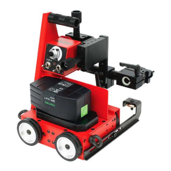
FDV 15 MF Vertical torch Handle adjustment unit On-board control unit Universal torch holder Horizontal torch adjustment unit Battery pack (14.4V / 3Ah) Guide wheels Truck with Lifting eye for securing the 4-wheel drive driving vehicle Driving vehicle FDV 15 MF... -
Page 12: Control Elements And Connections
(4) Toggle switch Start LEFT / STOP / Start RIGHT For starting and stopping the automa- tic program sequence. Driving vehicle FDV 15 MF control panel AC-ACvoltage The voltage transformer allows the charger to be operated using 110 V and 120 V mains transformer supplies. -
Page 13: Charger And Battery Pack
Charger and CAUTION! The charger may be damaged if the wrong supply voltage battery pack is used. The FDV MF charger is designed for a supply voltage of 230 V. Directly con- necting the charger to a 110 / 120 V mains supply can cause serious material damage. -
Page 14: Welding Position And Seam Tracking
Welding position and seam tracking Possible The 4-wheel drive and built-in permanent magnet ensure that the driving vehicle adheres welding optimally to the workpiece and guarantee the best possible traction. The following weld- positions ing positions are possible. IMPORTANT! In vertical operation, the driving vehicle must be secured by a load secur- ing device with a locking function to prevent it from falling. -
Page 15: Guidance Of The Driving Vehicle
Possible welding positions (continued) Inside of container with minimum diameter of 2500 mm NOTE! When used inside a container, the container must be turned in the op- posite direction and at the same speed. IMPORTANT! Use of the driving vehicle in the "PE" overhead position is prohibited. Guidance of the The guide wheels automatically track the torch in the filled joint. - Page 16 Guidance of the driving vehicle (continued) Guidance on angle piece (vertical) or rail Guidance on outside vertical surface Guidance on outside of curve with minimum diameter Guidance on inside of curve with minimum diameter of 5000 mm of 5000 mm NOTE! When guided on a hori- zontal angle piece, the welding torch must only be placed on the...
-
Page 17: Guidance Of The Driving Vehicle With Optional Lateral Guides
Guidance of the driving vehicle with optional lateral guides Lateral guide, tiltable Lateral guide for edge Lateral guide, standard / with magnet Lateral guide with flexible guide rail Lateral guide for flexible rail (2 pc.) (1850 mm / 72.84 in) Magnet block for guiding rail Guiding for flexible rail (1850 mm / 72.84 in) IMPORTANT! 10 magnet blocks per rail are necessary! -
Page 18: Preparing The Driving Vehicle
Preparing the driving vehicle Fitting the guide rails FDV-15 MF driving vehicle 1. Use M5 x 14 allen screws and a 5.5 shim to attach the guide rails to the driving vehicle. 2. Tighten the screws using a size 5 allen key. See „Adjusting the guide wheels“ for information on how to set the guide wheels. -
Page 19: Fitting The Brushes (Option)
Fitting the brushes (option) FDV-15 MF driving vehicle with brushes NOTE! The brush may be fitted to either the front or rear of the driving vehicle. 1. Remove the M5 x 14 (a) screws using a size 5 allen key. 2. -
Page 20: Fitting The Lateral Guides (Option)
Fitting the lateral All lateral guides for the FDV 15 carriage are fastened with the M5 x 14 fixing screws guides with washer. (Option) The lateral guides are mounted on both front sides of the carriage. Tighten the fixing screws with a size 5 allen key. Lateral guide, tiltable Lateral guide for edge Lateral guide, magnetic... -
Page 21: Fitting Lateral Guides With Flexible Guide Rail (Option)
Fitting lateral The lateral guides, which are used with guide rail, are fixed with the M5 x 14 fixing guides with screws with washers. flexible guide rail Tighten the screws with the 5 mm allen key. (Option) The flexible guide rail is fixed with magnet blocks. 10 magnet blocks are necessary for one rail (1850 mm / 72.84 in), to ensure a secure fit. -
Page 22: Connecting The Charger To The Mains Supply
Connecting the CAUTION! The charger may be damaged if the wrong supply voltage charger to the is used. mains supply The FDV MF charger is designed for a supply voltage of 230 V. Directly con- necting the charger to a 110 / 120 V mains supply can cause serious material damage. -
Page 23: Insert Battery Pack In Driving Vehicle Docking Station
Charge the 2. Push the battery pack into the charger battery pack docking station until it engages with (continued) the retainer (b) in the upper recess. The battery pack charges up. The signal lamp flashes GREEN during the charging process. IMPORTANT! The battery pack is fully charged after a charging time of 45 minutes. -
Page 24: Adjusting The Guide Wheels
Adjusting the 5 - 10 mm guide wheels Direction of travel Adjusting the guide wheels 1. Undo the fastening screws (a) 2. Extend the guide wheels (b) to the desired length. To ensure that the driving vehicle keeps to the chosen direction, the extended guide wheels must be extended by at least 5 - 10 mm (see diagram). -
Page 25: Attach Fall Protection (Vertical Operation)
Attach fall IMPORTANT! In vertical operation, the driving vehicle must be secured by a load secur- protection ing device with a locking function to prevent it from falling. The load securing device must (vertical be designed for the total weight of the vehicle. The manufacturer accepts no liability for operation) any damage to persons or property resulting from vertical use of the driving vehicle with- out a load securing device. -
Page 26: Driving Vehicle Strain Relief
Driving vehicle To attain optimum wirefeed, observe the following when laying the hose pack: strain relief Do not allow the hose pack to become kinked Always lay the hose pack as straight as possible Suspend the hose pack (it must not come into contact with the floor), use balancers and hose pack holders (e.g. -
Page 27: Start-Up
Start-up Check the WARNING! Operating the equipment incorrectly can cause serious injury and connections damage. Do not use the functions described until you have thoroughly read and understood the following documents: these operating instructions all the operating instructions for the system components, especially the safety rules The following activities and work steps apply to the installed system. -
Page 28: Carry Out Test Run
Carry out Perform a test run to check that all system components work together correctly. This is test run done without an arc and thus allows you to check all movements during the process: 1. Set the "Start LEFT / STOP / Start RIGHT" toggle switch to the de- sired direction - The test run starts. -
Page 29: Troubleshooting
Troubleshooting General In the event of faults, note that the functioning of the entire system depends on many additional components (power source, wire-feed unit, etc.) that are also potential sources of problems. Basic require- Connections established between separate system components ments for the System components are supplied with electricity and the mains voltage for each system to work... - Page 30 Driving vehicle "Control unit ON" signal lamp is lit but machine does not work (continued) Cause: "Start LEFT / STOP / Start RIGHT" toggle switch is in the "STOP" position. Remedy: Turn the toggle switch to the required direction. Cause: Traversing speed is set to "0".
-
Page 31: Maintenance And Care
WARNING! Risk of injury and damage from incorrectly performed main- tenance. All maintenance on the FDV 15 MF driving vehicle must only be carried out by trained technicians. It is essential to adhere to the maintenance intervals and maintenance procedures. The manufacturer accepts no liability for any damage caused by inadequate or poorly performed maintenance. -
Page 32: Driving Vehiclecomponents
Driving vehicle components... -
Page 33: Fdv-Mf Charger
Fronius Customer Service or at officially-authorised disposal sites. The battery packs are then recycled. -
Page 34: Technical Data
Technical data FDV 15 MF IMPORTANT! Standard version of FDV 15 MF carriage is not suitable for preheated workpieces from 50°C (122°F)! Driving vehicle supply voltage 14.4V / 3Ah (battery pack) Max. load 15 kg Pulling force (horizontal/vertical) 150 N / 100 N... -
Page 35: Fdv 15 Mf Dimensions
FDV 15 MF dimensions 220 mm 228 - 256 mm 220 - 248 mm 29 mm 208 - 280 mm 24 mm 28,5 mm 16 mm 24 mm... - Page 37 Spare parts list, circuit diagram FDV-15 MF...
- Page 39 Carriage FDV 15 MF 8,045,369...
- Page 40 Carriage FDV 15 MF 8,045,369 48,0005,1207 48,0005,1691...
- Page 41 Lateral guides Lateral guide, tiltable (2 pc.) Art. Nr. 48,0005,1889 (2) Lateral guide for edge (2 pc.) Art. Nr. 48,0005,1887 (3) Lateral guide, magnetic (2 pc.) Art. Nr. 48,0005,1891 Lateral guide with guide rail: Guide arm for flexible guide rail 1850 mm / 72.84 in (2 pc.) Art.
- Page 42 FDV 15 MF...
-
Page 43: Eu-Declaration Of Conformity
EU-Declaration of conformity... - Page 44 FRONIUS INTERNATIONAL GMBH TechSupport Automation www.fronius.com www.fronius.com/addresses...
Need help?
Do you have a question about the FDV 15 MF and is the answer not in the manual?
Questions and answers