Table of Contents
Advertisement
Quick Links
5-INTERFACE
PWR_NTC
3-SENSORS
SENS_I2C_SCK
SENS_I2C_SDA
LIS2DW12_INT
SENS_I2C_SCK_SWITCH
SENS_I2C_SDA_SWITCH
SENS_INT
4-POWER MANAGEMENT
STBC02_NTC
MURATA module
F
or VDD_TCXO connection:
Option1: Connect VDD_TCXO to VDD (assembly R107-
R106 unmount)
Option2: Connect VDD_TCXO to PA12 to make sure MCU
can control TCXO on/off (assembly R106- R107
unmount)
R107
VDD_TCXO
LORA_VDD
SMD 0201
U100
R106
54
0 NM
GND5
SMD 0201
55
GND6
56
GND7
57
GND8
GND
USB_DP
1
PA12/USB_DP
USB_DM
2
PA11/USB_DM
3
GND
GND
4
VDD_USB
VDD_USB
VDD
5
D_VDD
VDD_MCU
6
LORA_VDD
VDD_RF
7
GND
GND11
DBG_SX1276_DIO2
8
DBG_SX1276_DIO2
DBG_SX1276_DIO3
9
DBG_SX1276_DIO3
DBG_SX1276_DIO4
10
DBG_SX1276_DIO4
DBG_SX1276_DIO5
11
DBG_SX1276_DIO5
DBG_SX1276_DIO1
12
DBG_SX1276_DIO1
TP104
TP101
TP100
CMWX1ZZABZ-078
0 NM
R113
0 NM R114
TP105
D_VDD
C104
C103
C102
10µF
1µF
100nF
smc0603
SMD 0402
SMD 0201
GND
LORA_VDD
LoRa antenna
C116
C115
C117
10µF
1µF
100nF
smc0603
SMD 0402
SMD 0201
GND
D_VDD
VDD_USB
C110 and C112 are temporarily replaced by 0OHm resistor
R108
C112
SMD 0201
C113
C114
ANT
10uF
100nF
smc0603
SMD 0201
Assembly 0Ohm resistor
SMD 0402
GND
All information on this page is subject to the Evaluation Board License Agreement included in this document
Figure 1: STEVAL-STRKT01 circuit schematic (1 of 7)
1-LoRa MODULE
I2C1_SCL_1600
I2C1_SDA_1600
I2C1_SCL/PB8
I2C1_SDA/PB9
MCU_WKUP/PA0
I2C1_SCL_SENS
I2C1_SDA_SENS
PB6_INT
STUSB1600_VDD
STUSB1600_VDD
D_VDD
D_VDD
SENS_VDD
SENS_VDD
LORA_VDD
LORA_VDD
LIV3_VDD
MEM_VDD
Figure 2: STEVAL-STRKT01 circuit schematic (2 of 7)
GND
D_VDD
R105
R100
0 NM
R104
SMD 0201
0 NM
100K
SMD 0201
SMD 0201
TP115
SWD_SWCLK
SWD_SWDIO
LPTIM1_IN1/PB5
LPTIM1_ETR/PB6
LPTIM1_IN2/PB7
LPTIM1_OUT/PB2
R101
10K
36
PB9/I2C1_SDA
35
SMD 0201
PB8/I2C1_SCL
34
MCU_nRST
33
PA0/WKUP1
32
VREF+
VREF+
31
STSAFE_nRST
STSAFE_nRST
30
DBG_CRF2/PC2
DBG_CRF2/PC2
29
DBG_CRF3/PC1
DBG_CRF3/PC1
DBG_CRF1/PA1
28
DBG_CRF1/PA1
27
GND9
26
ANT
25
GND10
GND
GND
TP107
0
0
OSC_OUT
TP106
J100
1
3
GND1
GND
uFL connector NM
C110
GND
GND
Assembly 0Ohm resistor
SMD 0402
L103
L104
L NM
L NM
pi greek filter
SMD 0402
SMD 0402
GND
GND
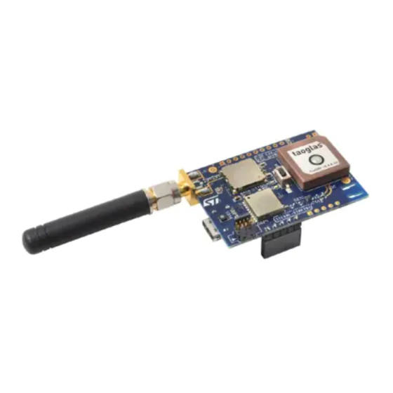
STEVAL-STRKT01 Schematic diagrams version 1 | sheet 1
PA4-LIV3RSTn
PA8/LIV3WKUP
ADC2/PA2/LIV3PPS
UART1_TX
UART1_RX
SPI2_NSS/I2S2_WS/PB12
SPI2_SCK/I2S2_CK/PB13
SPI2_MISO/I2S2_MCK/PB14
SPI2_MOSI/I2S2_SD/PB15
D_VDD
LORA_VDD
SENS_VDD
D_VDD
STUSB1600_VDD
R125
10K
SMD 0201
MCU_nRST
R1260 NM
STSAFE_nRST
D_VDD
C118
100nF
SMD 0201
SMD 0201
GND
D_VDD
MCU_WKUP/PA0
C105
1µF
SMD 0402
ANT
GND
TP108
TP109
TP110
NX2016SA 24MHZ / EXS00A-CS05544 NOT MOUNTED
TP111
TP112
Y100
R109
OSC_IN
3
1
GND
R110
0 NM
0 NM
SMD 0201
SMD 0201
C108
C109
10pF NM
10pF NM
smc0201
smc0201
GND
I2C1_SCL_SENS
I2C1_SCL/PB8
SENS_VDD
Exposed pad must be soldered to a
floating plane. Do NOT connect to
power or ground.
J101
Con_SMA
D_VDD
SENS_I2C_EN
I2C1_SDA_SENS
R116
1M
I2C1_SDA/PB9
2-LIV3
LIV3_RSTn
LIV3_WAKEUP
LIV3_PPS
UART1_TX
LIV3_RX
UART1_RX
LIV3_TX
6-MEMORY
SPI2_NSS/I2S2_WS/PB12
SPI_CS_M95
SPI2_SCK/I2S2_CK/PB13
SPI_SCK_M95
SPI2_MISO/I2S2_MCK/PB14
SPI_MISO_M95
SPI2_MOSI/I2S2_SD/PB15
SPI_MOSI_M95
MCU reset and wake up
MCU_WKUP/PA0
MCU_WKUP/PA0
MCU_nRST
MCU_nRST
SWD - USB
D_VDD
LORA_VDD
SWD_SWCLK
SWD_SWCLK
SWD_SWDIO
SWD_SWDIO
USB_DP
USB_DP
SENS_VDD
USB_DM
USB_DM
LIV3 communication
STUSB1600_VDD
ADC4/DAC1/PA4
PA4-LIV3RSTn
UART1_RX
UART1_RX
UART1_TX
UART1_TX
RCC_MCO/PA8
PA8/LIV3WKUP
ADC2/PA2
ADC2/PA2/LIV3PPS
Power and interface
LPTIM1_IN1/PB5
PB5-STBC02_SW_SL
ADC5/DAC2/PA5
BATMS_ADC5
ADC3/PA3
ADC3/PA3/STBC02nCHG
LPTIM1_OUT/PB2
PB2-USER_LED
Sensor connections
LPTIM1_ETR/PB6
PB6_INT
LPTIM1_IN2/PB7
LPTIM1_IN2/PB7
SPI
SPI2_SCK/I2S2_CK/PB13
SPI2_SCK/I2S2_CK/PB13
SPI2_MOSI/I2S2_SD/PB15
SPI2_MOSI/I2S2_SD/PB15
SPI2_MISO/I2S2_MCK/PB14
SPI2_MISO/I2S2_MCK/PB14
SPI2_NSS/I2S2_WS/PB12
SPI2_NSS/I2S2_WS/PB12
I²C
D_VDD
R102
R103
4K7
4K7
SMD 0201
SMD 0201
I2C1_SDA/PB9
I2C1_SDA/PB9
I2C1_SCL/PB8
I2C1_SCL/PB8
I2C1_SDA_SENS
I2C1_SDA_SENS
I2C1_SCL_SENS
I2C1_SCL_SENS
I2C1_SDA_1600
I2C1_SDA_1600
I2C1_SCL_1600
I2C1_SCL_1600
R1180 NM
I2C1_SCL/PB8
U101
R122
STUSB1600_VDD
0 NM
I2C1_SCL_1600
1
12
1S2
4S1
2
11
Vcc
GND
3
10
1600_I2C_EN
1-2SEL
3-4SEL
4
9
R124
2S1
3S2
1M
R121
R117
STG3692
0 NM
0 NM
I2C1_SDA/PB9
I2C1_SDA_1600
Page 1 of 7
Advertisement
Table of Contents

Related Manuals for ST STEVAL-STRKT01


Summary of Contents for ST STEVAL-STRKT01
- Page 1 STEVAL-STRKT01 Schematic diagrams version 1 | sheet 1 Figure 1: STEVAL-STRKT01 circuit schematic (1 of 7) 5-INTERFACE PWR_NTC 1-LoRa MODULE 2-LIV3 PA4-LIV3RSTn LIV3_RSTn PA8/LIV3WKUP LIV3_WAKEUP ADC2/PA2/LIV3PPS LIV3_PPS UART1_TX UART1_TX LIV3_RX UART1_RX UART1_RX LIV3_TX I2C1_SCL_1600 3-SENSORS I2C1_SDA_1600 SENS_I2C_SCK I2C1_SCL/PB8 SENS_I2C_SDA I2C1_SDA/PB9...
- Page 2 STEVAL-STRKT01 Schematic diagrams version 1 | sheet 2 Figure 3: STEVAL-STRKT01 circuit schematic (3 of 7) LIV3_VDD_IO LIV3_VDD_IO U200 R226 LIV3_VDD SYS_RSTn R221 GND_RF_10 SYS_RSTn LIV3_RSTn 0 NM L202 RF_IN RF_IN 27nH R214 GND_RF_12 VCC_IO C206 C207 ANTOFF R200 100nF...
- Page 3 STEVAL-STRKT01 Schematic diagrams version 1 | sheet 3 Figure 5: STEVAL-STRKT01 circuit schematic (5 of 7) CEN : Charger STBC02 Li-Ion battery charger with LDO enable pin. Active high. 500 kO internal pull-up VDD_LDO (to LDO) ST1PS01EJR buck converter USB_5V...
- Page 4 STEVAL-STRKT01 Schematic diagrams version 1 | sheet 4 Figure 7: STEVAL-STRKT01 circuit schematic (7 of 7) MEM_VDD C601 C602 MEM_VDD 10µF 100nF smc0603 R603 SMD 0201 MEM_VDD U600 SPI_CS_M95 R6000 SPI_CS_M95 SMD 0201 SMD 0201 I2C2_SCL SPI_SCK_M95 R6010 SPI_SCK_M95 R602...
- Page 5 You may not sell, assign, sublicense, lease, rent or otherwise distribute the Evaluation Board for commercial purposes, in whole or in part, or use Evaluation Board in a production system, with the exception that if You are an authorized ST distributor, You may resell the Evaluation Board in compliance with the applicable terms and conditions.
- Page 6 ST may terminate this Agreement without notice if You breach this Agreement. Upon termination, You shall immediately destroy or return all copies of the software, firmware, and documentation of the Evaluation Board to ST and certify in writing to ST that You have done so.
- Page 7 Accordingly, in addition to any other remedies and damages available, You acknowledge and agree that ST may immediately seek enforcement of this Agreement in any jurisdiction by means of specific performance or injunction, without any requirement to post a bond or other security.
Need help?
Do you have a question about the STEVAL-STRKT01 and is the answer not in the manual?
Questions and answers