Table of Contents
Advertisement
Quick Links
UM2541
User manual
Getting started with the STEVAL-STRKT01 LoRa® IoT tracker
Introduction
®
The
STEVAL-STRKT01
LoRa
IoT tracker is designed and optimized to implement the latest technologies in IoT tracker
applications such as asset, people and animal tracking as well as fleet management.
The evaluation board simplifies prototyping, evaluation and development of tracker innovative solutions. It comes with
comprehensive software, firmware libraries, tools, battery, cables and plastic case.
®
Thanks to the
STM32L072CZ
embedded in the CMWX1ZZABZ-091 LoRa
module (by Murata), the STEVAL-STRKT01 allows
acquiring position, managing geofence and data logging from
Teseo-LIV3F
GNSS module and monitoring motion (LIS2DW12)
and environmental
(HTS221
and LPS22HB) sensors.
The board also transmits and receives data, configurations and events to and from the cloud over a LoRaWAN™ network, or
stores data locally in the
M95M02-DR
EEPROM.
The STEVAL-STRKT01 is a LiPo battery operated solution and implements low power strategies thanks to an enhanced power/
battery management design, based on the
STBC02
battery charger and the
ST1PS01
step-down converter, to ensure long
battery autonomy. The
STUSB1600A
addresses 5 V USB Type-C port management and offers high voltage protection pins.
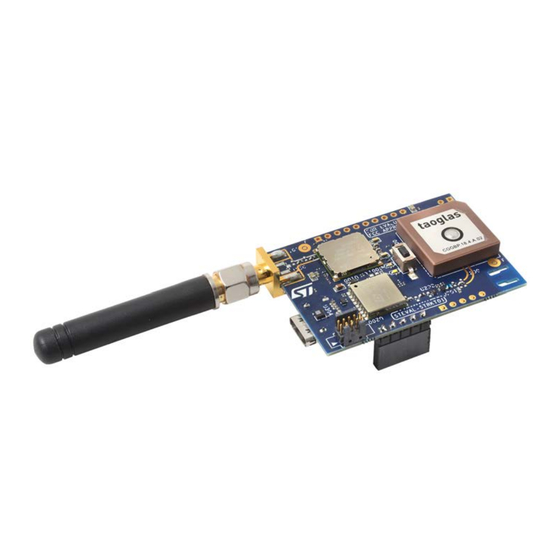
Figure 1.
STEVAL-STRKT01 evaluation board
UM2541 - Rev 2 - December 2019
www.st.com
For further information contact your local STMicroelectronics sales office.
Arrow.com.
Downloaded from
Advertisement
Table of Contents

Related Manuals for ST STEVAL-STRKT01

Summary of Contents for ST STEVAL-STRKT01
- Page 1 The board also transmits and receives data, configurations and events to and from the cloud over a LoRaWAN™ network, or stores data locally in the M95M02-DR EEPROM. The STEVAL-STRKT01 is a LiPo battery operated solution and implements low power strategies thanks to an enhanced power/ battery management design, based on the STBC02 battery charger and the...
-
Page 2: Getting Started
Optimized IoT tracker solution over LoRaWAN™ network with simultaneous multi-constellation GNSS positioning and geofencing support • Battery operated solution with smart power management architecture • First IoT ST reference embedding a USB Type-C connector and a port controller • Environmental and motion sensors • Data logging •... -
Page 3: Steval-Strkt01 Package
UM2541 STEVAL-STRKT01 package Figure 2. STEVAL-STRKT01 package Figure 3. STEVAL-STRKT01 components UM2541 - Rev 2 page 3/47 Arrow.com. Arrow.com. Arrow.com. Downloaded from Downloaded from Downloaded from... -
Page 4: How To Use And Configure The Board
UM2541 How to use and configure the board How to use and configure the board 1.3.1 Hardware setup To start up the system and run the demo: UM2541 - Rev 2 page 4/47 Arrow.com. Arrow.com. Arrow.com. Arrow.com. Downloaded from Downloaded from Downloaded from Downloaded from... -
Page 5: Figure 4. Steval-Strkt01 Setup (1 Of 4)
How to use and configure the board Step 1. Set up the hardware, as shown below. Step 1a. Figure 4. STEVAL-STRKT01 setup (1 of 4) Step 1b. Figure 5. STEVAL-STRKT01 setup (2 of 4) Step 1c. UM2541 - Rev 2 page 5/47 Arrow.com. -
Page 6: Serial Port Configuration
UM2541 How to use and configure the board Figure 6. STEVAL-STRKT01 setup (3 of 4) Step 1d. Figure 7. STEVAL-STRKT01 setup (4 of 4) Step 2. Connect the LoRa antenna to connector J101. Step 3. Press switch SW400 to power on (for 1.250 s at least) 1.3.2... -
Page 7: Figure 8. Virtual Com Port Configuration
On the first run, take note of the DevEUI string necessary to identify the device. Step 4. For further steps of device registration and configuration, and gateway setup, refer to UM2487, freely available at www.st.com. UM2541 - Rev 2 page 7/47 Arrow.com. -
Page 8: Command List
Most commands do not need customization, except the ones to set the LoRa device EUI, the LoRa join EUI, the application key and the network key, the LoRa sending interval and data rate, as well as the RTC date and time. Table 1. STEVAL-STRKT01 command list Label Get/Set... - Page 9 UM2541 Command list Label Get/Set Description ASCII command It sets the LoRa sending interval (xxxxx is the interval expressed in ms). The syntax of the ASCII Set LoRa send !lorainterval-xxxxx command which sets the LoRa sending interval is: ! interval lorainterval-xxxxx<CR><LF>.
- Page 10 UM2541 Command list Label Get/Set Description ASCII command This command has effect on the feeding line (refer to 1600_POWER net in Section 4 Schematic diagrams) that enables the I²C communication with Type-C controller the USB Type-C port controller as well as its status !powertcctrl-x VDD is switched management.
- Page 11 L if the geofence is centered on ST Catania site coordinates !geofence-p-rrrrr Config geofence • C if the geofence is centered on ST Lecce site coordinates • X to disable geofence functionality Moreover if H, L or C is selected, the command must be completed with the ‘-‘...
-
Page 12: Hardware Description
PH0_OSC_IN pin by mounting R105. The STEVAL-STRKT01 can be equipped, if needed, with an external crystal oscillator: a 24 MHz oscillator with 20 pF capacitors can be added to the board (Y100, C108 and C109 are not fitted by default). -
Page 13: Lora Module
UM2541 LoRa module Figure 9. STEVAL-STRKT01 LoRa module and components (top view) Figure 10. STEVAL-STRKT01 LoRa module and components (bottom view) UM2541 - Rev 2 page 13/47 Arrow.com. Arrow.com. Arrow.com. Arrow.com. Arrow.com. Arrow.com. Arrow.com. Arrow.com. Arrow.com. Arrow.com. Arrow.com. Arrow.com. Arrow.com. - Page 14 TP106 The STEVAL-STRKT01 has an SMA antenna connector J101, that can be replaced by a U.FL connector by assembling J100. The PI greek filter on the RF path allows improving RF performance by tuning C110, C110, L103, L104.
-
Page 15: Power Management
UM2541 Power management Figure 13. STEVAL-STRKT01 LoRa antenna schematic diagram J100 GND1 C110 and C112 are temporarily replaced by 0OHm resistor uFL connector NM C112 C110 J101 Con_SMA Assembly 0Ohm resistor Assembly 0Ohm resistor SMD 0402 SMD 0402 L104 L103... - Page 16 UM2541 Power management Figure 14. STBC02 schematic diagram CEN : Charger enable pin. Active high. 500 kO internal pull-up VDD_LDO (to LDO) USB_5V CHG : Charging/fault flag. Active low (open drain output) C400 3.0 V 150 mA (max) WAKE-UP : 10uF R421 Shipping mode...
-
Page 17: Figure 16. Steval-Strkt01 Block Diagram
The microcontroller plays a key role at power management stage. Acting on the STBC02 device SW_SEL pin, it allows switching on and off the SPDT switches feeding downstream sub-circuits as requested by the application. Figure 16. STEVAL-STRKT01 block diagram The sub-circuits that can be activated according to the application programmed tasks are: •... -
Page 18: Memory
UM2541 Memory Memory The M95M02 devices are electrically erasable programmable memories (EEPROMs) organized as 262144 x 8 bits, accessed through the SPI bus. The M95M02 can operate with a supply range from 1.8 to 5.5 V. These devices are guaranteed over the -40/+85 °C temperature range. -
Page 19: Usb Type-C
Figure 18. USB Type-C™ plug configuration Figure 19. USB Type-C™ receptacle configuration ® STEVAL-STRKT01 LoRa IoT tracker embeds a USB Type-C™ receptacle and a port controller. Both devices, according to the USB Type-C™ specification, support the following features: • consumer power role to recharge the on-board battery •... - Page 20 UM2541 Interface Figure 20. USB Type-C™ sub-circuit schematic diagram C503 STUSB1600_VDD 1µF STUSB1600_VDD C504 1µF C505 D_VDD D_VDD 1µF STUSB1600_VDD VDD_USB_TYPEC U500 CN500 D503 USB TYPE-C STUSB1600_VDD ESDALC5-1BF4 R519 GND4 GND1 VBUS_USB SMD 0201 VBUS_SENSE CC1DB RX1+ TX1+ STUSB1600_VDD RX1- TX1- VBUS_USB A_B_SIDE...
- Page 21 UM2541 Interface Figure 21. STEVAL-STRKT01 load switch schematic diagram VDD_USB_TYPEC Q500 Q501 STL4P3LLH6 STL4P3LLH6 USB_5V VBUS_USB R504 C507 C500 220nF NM 10uF MOUSER MOUSER R505 SINK_EN The applied input voltage allows the loads connected to SYS and LDO pins of STBC02 devices to be supplied, thus enabling proper system operations and starting the charging cycle, signaled by the CHG pin which starts toggling.
-
Page 22: Buttons And Leds
SW400 to turn the board on when it is supplied only by the battery (keep the button pressed for 1.250 s). After the power on, SW400 becomes a generic user button. FP-ATR-LORA1 uses it to reset the system. Figure 23. STEVAL-STRKT01 buttons and LEDs (top view) UM2541 - Rev 2 page 22/47 Arrow.com. -
Page 23: Swd And Expansion Connectors
UM2541 Interface Figure 24. STEVAL-STRKT01 buttons and LEDs (bottom view) LED D500 is the white user LED used by FP-ATR-LORA1 to provide indication of LoRa transmission status: • Slow blinking (2 seconds) = not joined • Fast blinking (0.5 seconds) = joined •... -
Page 24: Figure 26. Steval-Strkt01 Connectors (Top View)
UM2541 Interface Figure 26. STEVAL-STRKT01 connectors (top view) Figure 27. STEVAL-STRKT01 connectors (bottom view) UM2541 - Rev 2 page 24/47 Arrow.com. Arrow.com. Arrow.com. Arrow.com. Arrow.com. Arrow.com. Arrow.com. Arrow.com. Arrow.com. Arrow.com. Arrow.com. Arrow.com. Arrow.com. Arrow.com. Arrow.com. Arrow.com. Arrow.com. Arrow.com. Arrow.com. Arrow.com. -
Page 25: Update Via St-Link/V2 In-Circuit Debugger/Programmer
Step 3b. Supply the STEVAL-STRKT01 via a Type-C USB cable (and a Type-C to Type-A adapter if needed) Step 4. Connect the ST-LINK/V2 to a PC via a Type-A/mini B cable UM2541 - Rev 2 page 25/47 Arrow.com. Arrow.com. Arrow.com. -
Page 26: Update Via St-Link/V3 In-Circuit Debugger/Programmer
To perform the update via ST-LINK/V3 you first have to combine it with the adapter (MB1441 plus MB1440, shown Figure 30. Hardware configuration for STEVAL-STRKT01 firmware update using an ST-LINK/V3 programmer Step 1. Connect the 5-pin flat cable (male side) to... -
Page 27: Update Via Stm32 Nucleo-64 On-Board St-Link Programmer
Step 4. Connect the ST-LINK/V3 to a PC via a Type-A/micro B cable Figure 30. Hardware configuration for STEVAL-STRKT01 firmware update using an ST-LINK/V3 programmer 3.4.6 Update via STM32 Nucleo-64 on-board ST-LINK programmer Step 1. Connect the 5-pin flat cable (male side) to... -
Page 28: Gnss
UM2541 GNSS Figure 31. Hardware configuration for STEVAL-STRKT01 firmware update using STM32 Nucleo-64 on- board ST-LINK programmer GNSS Teseo-LIV3F tiny GNSS module represents an affordable, easy-to-use, global navigation satellite system (GNSS) module, embedding a TeseoIII single die standalone positioning receiver IC. - Page 29 UM2541 GNSS Figure 32. STEVAL-STRKT01 Teseo-LIV3F components (top view) The module is powered by the VDD_BUCK domain (3.3 V output from ST1PS01) through one of the switches embedded in the STBC02 (STBC02_SW1_OA). This enables the low power strategies implemented in the firmware that permit the complete shutdown of the Teseo-LIV3F module.
-
Page 30: Sensors
UM2541 Sensors Figure 34. STEVAL-STRKT01 Teseo-LIV3F module RF path schematic diagram LIV3_VDD_RF LIV3_VDD_RF R215 R210 C208 R216 0 NM ANTOFF 120pF SMD 0402 C203 R217 L201 100nF 100nH NM SMD 0201 SMD 0201 U201 U202 C204 C200 J200 BGA725L6 L200... -
Page 31: Hts221
The sensing element consists of a polymer dielectric planar capacitor structure capable of detecting relative humidity variations and is manufactured using a dedicated ST process. The HTS221 is available in a small top-holed cap land grid array (HLGA) package guaranteed to operate over a temperature range from -40 to +120 °C. - Page 32 UM2541 Sensors The LPS22HB is supplied by SENS_VDD power domain, connected to the VDD_BUCK domain (3.3 V output from ST1PS01) through one of the switches embedded in the STBC02 (STBC02_SW2_OB). This enables the low power strategies implemented in the firmware, by cutting the power supply of the sensors when not used. The I²C bus (SENS_I2C_SCK_SWITCH and SENS_I2C_SDA_SWITCH), shared with HTS221, is connected to LoRa module PB8 and PB9 pins.
- Page 33 UM2541 Schematic diagrams Schematic diagrams Figure 38. STEVAL-STRKT01 circuit schematic (1 of 7) 5-INTERFACE PWR_NTC 1-LoRa MODULE 2-LIV3 PA4-LIV3RSTn LIV3_RSTn PA8/LIV3WKUP LIV3_WAKEUP ADC2/PA2/LIV3PPS LIV3_PPS UART1_TX UART1_TX LIV3_RX UART1_RX UART1_RX LIV3_TX I2C1_SCL_1600 3-SENSORS I2C1_SDA_1600 SENS_I2C_SCK I2C1_SCL/PB8 SENS_I2C_SDA I2C1_SDA/PB9 LIS2DW12_INT MCU_WKUP/PA0 6-MEMORY...
-
Page 34: Figure 39. Steval-Strkt01 Circuit Schematic (2 Of 7)
UM2541 Schematic diagrams Figure 39. STEVAL-STRKT01 circuit schematic (2 of 7) MCU reset and wake up MCU_WKUP/PA0 D_VDD MCU_WKUP/PA0 MCU_nRST MCU_nRST MURATA module R105 D_VDD D_VDD SWD - USB R100 0 NM R104 SMD 0201 0 NM 100K or VDD_TCXO connection:... -
Page 35: Schematic Diagrams
UM2541 Schematic diagrams Figure 40. STEVAL-STRKT01 circuit schematic (3 of 7) LIV3_VDD_IO LIV3_VDD_IO U200 R226 LIV3_VDD SYS_RSTn R221 LIV3_RSTn GND_RF_10 SYS_RSTn 0 NM L202 RF_IN RF_IN 27nH R214 GND_RF_12 VCC_IO C206 C207 ANTOFF R200 100nF 100pF AntOFF VBATT C209 SMD 0201... -
Page 36: Figure 42. Steval-Strkt01 Circuit Schematic (5 Of 7)
UM2541 Schematic diagrams Figure 42. STEVAL-STRKT01 circuit schematic (5 of 7) CEN : Charger STBC02 Li-Ion battery charger with LDO enable pin. Active high. 500 kO internal pull-up VDD_LDO (to LDO) ST1PS01EJR buck converter USB_5V CHG : Charging/fault flag. Active low... - Page 37 UM2541 Schematic diagrams Figure 43. STEVAL-STRKT01 circuit schematic (6 of 7) Battery connector VBAT VBAT D_VDD CN501 R514 0 NM BATT+ J501 nRESET PWR_NTC nRESET PWR_NTC SWD_SWDIO SWD_SWDIO R5150 SMD 0201 SWD_SWDIO SMD 0201 LED_User SWD_SWCLK VBUS_USB CN502 ST1600_I2C_SCKUART_RX SWD_SWCLK 4...
-
Page 38: Bill Of Materials
UM2541 Bill of materials Bill of materials Table 5. STEVAL-STRKT01 bill of materials Item Q.ty Ref. Part/Value Description Manufacturer Order code Wurth CN500 USB Type-C 632723300011 Electronics Sullins 5-pin 5x1 2.54 CN501 Female header Connector PPPC051LFBN-RC mm pitch Solutions Sullins 10-pin 10x1 2.54... - Page 39 UM2541 Bill of materials Item Q.ty Ref. Part/Value Description Manufacturer Order code 220 nF SMD Capacitor (not C507 0603 50 V ±10% mounted) D401 SMD 0402 Red LED KingBright KPHHS-1005SURCK ZENER_3V07 D402 Zener diode Nexperia BZX384-B3V0, 115 SOD323 0.02 Single-line low ESDALC6V1-1U capacitance D403, D501...
- Page 40 UM2541 Bill of materials Item Q.ty Ref. Part/Value Description Manufacturer Order code Murata 27 nH SMD L202 Electronics LQG15HS27NJ02D 0402 0.05 North America 2.2 µH SMD Wurth 74438323022 / L401 1008 1.3 A 0.2 Electronics/ TDK VLS252010HBX-2R2M 470 Ohms @ L403 100MHz SMD Murata...
- Page 41 UM2541 Bill of materials Item Q.ty Ref. Part/Value Description Manufacturer Order code R116, R124, 1M SMD 0201 Film resistors R410 ±1% 0 SMD 0402 R209 Film resistor ±1% 0 NM SMD 0402 Film resistors R213, R218 ±1% (not mounted) R222, R223, 1K NM SMD Film resistors R224, R225...
- Page 42 UM2541 Bill of materials Item Q.ty Ref. Part/Value Description Manufacturer Order code CMWX1ZZABZ- U100 LoRa module Murata CMWX1ZZABZ-078 LoRA42X125X1 16X017 STG3692 Low voltage U101 QFN16L (2.6mm quad SPDT STG3692QTR x 1.8mm) switch TESEO-LIV3F LCC 18 pin Tiny GNSS U200 TESEO-LIV3F package module (9.7x10.1)
-
Page 43: Revision History
Revision history Table 6. Document revision history Date Version Changes 15-Feb-2019 Initial release. Updated Table 1. STEVAL-STRKT01 command list Section 3.4.3 SWD and expansion connectors. 09-Dec-2019 Added Section 3.4.4 Update via ST-LINK/V2 in-circuit debugger/programmer, Section 3.4.5 Update via ST-LINK/V3 in-circuit debugger/programmer Section 3.4.6 Update via STM32 Nucleo-64 on-... -
Page 44: Table Of Contents
SWD and expansion connectors ..........23 3.4.4 Update via ST-LINK/V2 in-circuit debugger/programmer......25 3.4.5 Update via ST-LINK/V3 in-circuit debugger/programmer. - Page 45 ST-LINK/V2 programmer and STEVAL-STRKT01 pinout ........
- Page 46 STEVAL-STRKT01 LoRa module and components (bottom view) ....... . 13...
- Page 47 ST’s terms and conditions of sale in place at the time of order acknowledgement. Purchasers are solely responsible for the choice, selection, and use of ST products and ST assumes no liability for application assistance or the design of Purchasers’...
Need help?
Do you have a question about the STEVAL-STRKT01 and is the answer not in the manual?
Questions and answers