Table of Contents
Advertisement
Quick Links
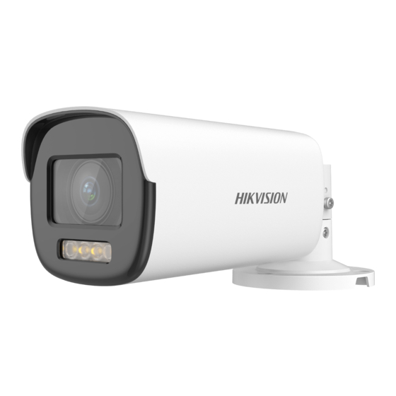
Motorized Varifocal Camera
User Manual
Thank you for purchasing our product. If there are any
questions, or requests, do not hesitate to contact the
dealer.
This manual applies to the models below:
Type I Camera
Type II Camera
Type III Camera
This manual may contain several technical mistakes or
printing errors, and the content is subject to change
without notice. The updates will be added to the new
version of this manual. We will readily improve or
update the products or procedures described in the
manual.
2 MP ColorVu PoC
Type
User Manual
Model
DS-2CE19DF8T-AZE
DS-2CE79DF8T-AZE
DS-2CE59DF8T-AVPZE
01000020200619
Advertisement
Table of Contents

Related Manuals for HIKVISION DS-2CE19DF8T-AZE


Summary of Contents for HIKVISION DS-2CE19DF8T-AZE
- Page 1 This manual applies to the models below: Type Model Type I Camera DS-2CE19DF8T-AZE Type II Camera DS-2CE79DF8T-AZE Type III Camera DS-2CE59DF8T-AVPZE This manual may contain several technical mistakes or printing errors, and the content is subject to change without notice.
- Page 2 The information contained in the Manual is subject to change, without notice, due to firmware updates or other reasons. Please find the latest version of this Manual at the Hikvision website (https://www.hikvision.com/). Please use this Manual with the guidance and assistance of professionals trained in supporting the Product.
-
Page 3: Regulatory Information
UNSAFE NUCLEAR FUEL-CYCLE, OR IN SUPPORT OF HUMAN RIGHTS ABUSES. IN THE EVENT OF ANY CONFLICTS BETWEEN THIS MANUAL AND THE APPLICABLE LAW, THE LATER PREVAILS. Regulatory Information FCC Information Please take attention that changes or modification not expressly approved by the party responsible for compliance could void the user’s authority to operate the equipment. - Page 4 Safety Instruction These instructions are intended to ensure that user can use the product correctly to avoid danger or property loss. The precaution measure is divided into “Warnings” and “Cautions”. Warnings: Serious injury or death may occur if any of the warnings are neglected.
-
Page 5: Installation
To avoid heat accumulation, good ventilation is required for the operating environment. Keep the camera away from liquid while in use for non-water-proof device. While in delivery, the camera shall be packed in its original packing, or packing of the same texture. Mark Description Table 0-1 Mark Description Mark... - Page 6 Make sure that the device in the package is in good condition and all the assembly parts are included. Make sure that all the related equipment is power-off during the installation. Check the specification of the products for the ...
- Page 7 2. (Optional) For cement wall, drill the screw holes with a 5.5 mm drill and insert the supplied wall plugs. 3. (Optional) Drill the cable hole, when the cables are routed through the wall. 4. Take apart the junction box. 5.
- Page 8 Figure 2-6 Secure Base to Ceiling 4. Loosen the screw on the base to adjust the view angle. Figure 2-7 Loosen Screw 5. Power on the camera to adjust the view angle according to the figure below. Figure 2-8 3-Axis Adjustment 1).
- Page 9 3. (Optional) Drill the cable hole, when the cables are routed through the ceiling. 4. Secure the junction box body on the ceiling with four PA4 × 25 screws that come with the junction box. Figure 2-10 Fix Junction Box on Ceiling 5.
- Page 10 Figure 2-14 Finish Installation 2.2.3 Wall Mounting Before you start: You need to purchase a wall mount in advance. Steps: Drill Φ 10 mm screw holes in the wall where you want to install the wall mount. 2. Use four M6 expansion bolts to fix the wall mount onto the wall.
- Page 11 3. Repeat steps 5 to 9 of 2.2.2 Ceiling Mounting with Junction Box to finish the installation. Figure 2-18 Finish Installation Installation of Type III Camera 2.3.1 Ceiling Mounting Without Junction Box Steps: 1. (Optional) For cement ceiling, drill the screw holes with a 5.5 mm drill and insert the supplied wall plugs.
- Page 12 6. Tighten the screw. Figure 2-22 Tighten Screw 7. Power on the camera to adjust the view angle according to the figure below. Pan Position [0° to 355°] Tilt Position [0° to 75°] Rotation Position [0° to 355°] Figure 2-23 3-Axis Adjustment 8.
-
Page 13: Menu Description
You need to purchase a pendant mount in advance. Steps: 1. Install the bracket. Secure the base plate to the installation adapter of the bracket. Fix the bracket on the ceiling. Screw the installation adapter to the bracket. iii. Figure 2-26 Install Bracket 2. -
Page 14: Video Format
ZOOM/ FOCUS VIDEO FORMAT EXPOSURE MODE EXPOSURE ANTI - BANDING BACK EXIT SAVE & EXIT IMAGE MODE WHITE BALANCE BRIGHTNESS CONTRAST VIDEO SHARPNESS MAIN MENU SETTINGS SATURATION 3DNR MIRROR BACK EXIT SAVE & EXIT LIGHT THRESHOLD SMART LEVEL LIGHT BACK EXIT SAVE &... -
Page 15: Video Settings
3.3 EXPOSURE EXPOSURE MODE You can set the EXPOSURE MODE to GLOBAL, BLC, HLC, WDR, or HLS. GLOBAL GLOBAL refers to the normal exposure mode which adjusts lighting distribution, variations, and non-standard processing. BLC (Backlight Compensation) BLC (Backlight Compensation) compensates light to the object in the front to make it clear, but this may cause over-exposure of the background where the light is strong. - Page 16 WHITE BALANCE White balance, the white rendition function of the camera, is to adjust the color temperature according to the environment. It can remove unrealistic color casts in the image. You can set WHITE BALANCE mode to AUTO, or MANUAL. AUTO ...
-
Page 17: Motion Det
THRESHOLD The higher the threshold is, the more sensitive the device is to dark environment. LEVEL You can adjust the maximum brightness of supplement light. 3.6 FUNCTIONS MOTION DET MOTION DET refers to motion detection. With motion detection feature, motion can be detected in any part of a camera's view.
Need help?
Do you have a question about the DS-2CE19DF8T-AZE and is the answer not in the manual?
Questions and answers