Table of Contents
Advertisement
Quick Links
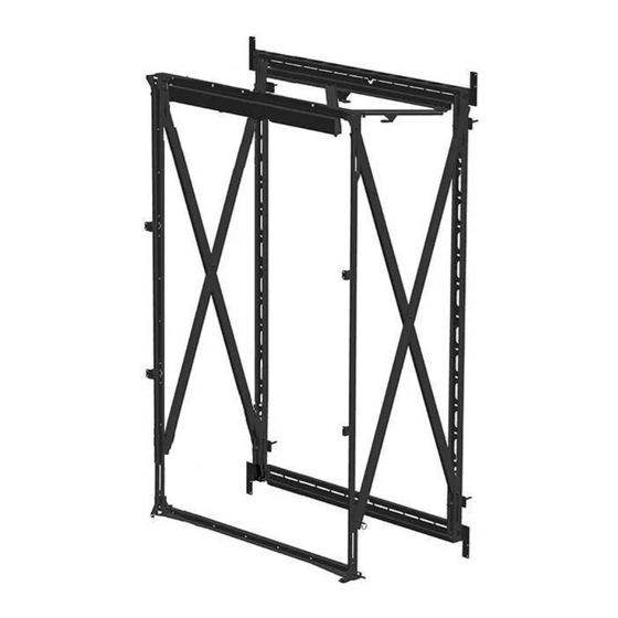
PLW 1003 - 1x3 LED video wall mount
EN
DE Montageanleitung
FR
NL
ES
IT
PT Manual de montagem
EL Οδηγίες συναρμογής
SV
PL
RU
Инструкция по сборке и установке
CZE Návod k montáži
SK
Návod na montáž
HU Szerelési előírás
TR
Montaj kılavuzu
RO
UK
Вказівки по монтажі
BG Инструкции за монтаж
設置の説明書
JA
ZH
MOUIN_PLW 1003 _V02
Advertisement
Table of Contents

Related Manuals for vogel's PLW 1003


Summary of Contents for vogel's PLW 1003
- Page 1 PLW 1003 - 1x3 LED video wall mount Инструкция по сборке и установке CZE Návod k montáži Вказівки по монтажі DE Montageanleitung PT Manual de montagem EL Οδηγίες συναρμογής Návod na montáž BG Инструкции за монтаж 設置の説明書 HU Szerelési előírás Montaj kılavuzu...
- Page 2 5/8”-10 x 2” Bolt 5/16” x 6” Lag Bolt 5/16” Washer 5/16” x 3” Lag with hole Bolt M6 x 20mm 1/4” x 2 1/2” M5 Allen Key M2 Allen Key Push Pin Socket Cap Wall Mount Wall Plate M5 x 6 mm Flat Head M5 x 10 mm Scre w M4 x 6 mm Set Screw Screw...
- Page 3 1) Extend the mount. 2) Install the 1/4” x 2 1/2” push pin (F) to keep the mount extended. Key Slot Place the wall mount over the lag bolt through the key slot hole. Lag Bolt Washer Flush Bolt Install the four (4) 5/8”-10 x 2” Bolt (A) with hole into the wall mount.
- Page 4 Before installing the 5/16” x 6” lag bolt and washer make sure the phillips screw is in the center of the slots. This will give 1/2” adjustments either up or down. Wall Plate Washer 5/16” x 6” Lag Bolt 1) Level the wall mount. 2) Place the wall bracket (M) between the wall mount and wall.
- Page 5 1) Use four (4) M6 x 16 mm flat socket head screws (N) on the first LED display to center it in place. 2) Install the second and third LED display unsing four (4) M6 x 20 mm socket cap screw in each LED display (E). 3) Optional to change the M6 x 16 mm flat socket head screws (N) to M6 x 20 mm socket cap screws E).
- Page 6 Install twelve (12) M4 x 6 mm set screws (L). You can adjust the panel in & out by using the M2 Allen key (H). OPTIONAL EXTENSIONS 1200 mm [47.24”] Linear Set Up Page 6...
- Page 7 Align the tabs with eachother. Install the spacer brackets (M) to the mount using eight (8) 6 mm flat head screws (J). Four (4) screws per bracket. Page 7...
- Page 8 Install the mounts together using four (4) M5 x 10 mm screws (K) and two (2) M8 x70 mm screws (O). To collapse the mount and secure, remove the push pin than install two (2) M5 x 10 mm screws (K). One screw per latch. Adjustments (GB) Subject to printing errors and technical amendments.
Need help?
Do you have a question about the PLW 1003 and is the answer not in the manual?
Questions and answers