Advertisement
OPERATING MANUAL
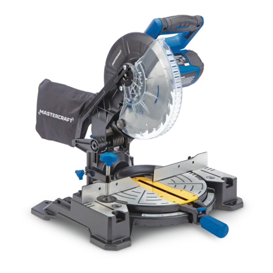
10" COMPOUND MITRE SAW
55-6847-0
Parts missing or damaged? Questions? Toll-Free Help Line – 1-800-689-9928
IMPORTANT:
Read through this operating manual carefully before using this tool. Pay close attention to all Safety
Instructions, Warnings, and Caution sections. Use this tool properly and only for its intended use.
Safety symbols in this manual are used to call attention to possible dangers. The safety
symbols and their explanations require the operator's full understanding. The safety warnings do
not, by themselves, eliminate any danger, nor are they a substitute for proper accident-prevention
measures.
This Safety Alert Symbol indicates caution, warning, or danger. Failure to obey a safety
warning can result in serious injury to the operator or to others. To reduce the risk of injury, fire, or
electric shock, always follow the safety precautions.
1
Advertisement
Table of Contents

Subscribe to Our Youtube Channel
Related Manuals for MasterCraft 55-6847-0


Summary of Contents for MasterCraft 55-6847-0
- Page 1 OPERATING MANUAL 10” COMPOUND MITRE SAW 55-6847-0 Parts missing or damaged? Questions? Toll-Free Help Line – 1-800-689-9928 IMPORTANT: Read through this operating manual carefully before using this tool. Pay close attention to all Safety Instructions, Warnings, and Caution sections. Use this tool properly and only for its intended use.
-
Page 2: Table Of Contents
TABLE OF CONTENTS Rules for Safe Operation………………………………. Page 3-7 Glossary of Woodworking Terms…………………….. Page 8 Description……………………………………....Page 8-9 Assembly……………………..……......Page 10-11 Adjustments..............Page 12 Operation....…………………......Page 13-19 Maintenance............... Page 19 Troubleshooting............Page 20 Repair Parts..............Page 20 Exploded View & Part List........... Page 21-22 Warranty…………………………………………………. -
Page 3: Rules For Safe Operation
RULES FOR SAFE OPERATION KNOW THE TOOL To operate this tool safely, read this operating manual and all the labels affixed to the Compound Mitre Saw before using it, and follow the instructions contained therein. Retain this manual for future reference. - Page 4 unintentionally contacted. WARNING: The operation of any tool can result in foreign objects being propelled into the eyes, which could result in severe eye damage. When operating a power tool, always wear safety goggles or safety glasses with side shields or a full face shield, if necessary. Check for damaged parts.
- Page 5 ELECTRICAL SAFETY Ground instruction: In the event of a malfunction or breakdown, grounding provides a path of least resistance for electric current reduce the risk of electric shock. This tool is equipped with an electric cord that has an equipment-grounding conductor and a grounding plug. The plug must be plugged into a matching outlet that is properly installed and grounded in...
- Page 6 a negative hook angle. IMPORTANT: Do not use thin-kerf blades. Thin-kerf blades can deflect and contact the guard, which can cause possible injury to the operator. Do not operate the Compound Mitre Saw until it is completely assembled and installed according to these instructions.
- Page 7 WARNING: To avoid electrical hazards, fire hazards, or damage to the tool, use proper circuit protection.
-
Page 8: Glossary Of Woodworking Terms
GLOSSARY OF TERMS FOR WOODWORKING Arbour: The revolving shaft on which a blade or cutting tool is mounted. Arbour Lock: Allows the user to stop the blade from rotating while tightening or loosening the arbour screw during blade replacement or removal. Bevel Cut: A cutting operation made with the blade at any angle other than 90°... - Page 9 Fig.1 ON/OFF switch Horizontal, rubberized D-handle Safety lock-off button Upper blade guard Blade-screw guard Saw blade Mounting holes Mitre table Mitre-angle scale Throat plate Mitre-angle indicator Mitre lock Clamp-mounting holes Fence Lower blade guard Spindle-lock button Stop latch Bevel-angle scale Bevel lock Bevel-angle indicator ▪...
-
Page 10: Assembly
ASSEMBLY WARNING: To reduce the risk of injury, always unplug the tool before attaching or removing accessories or making adjustments. Only use specifically recommended accessories. Dust Collection The saw is shipped with the dust-bag adapter attached to the dust ejection chute. Also shipped with the tool is an adapter for use with a shop vacuum. -
Page 11: Adjustments
Removing the blade (see Fig.5) WARNING: To reduce the risk of injury, always unplug the tool before removing and installing a blade. 1. Raise the saw head. Fig.5 2. Remove the upper screw on the blade-screw guard Inner flange (Fig.1, point 5) by turning it counter-clockwise with a Outer flange screwdriver. - Page 12 IMPORTANT: Do not use thin-kerf blades. Thin-kerf blades can deflect and contact the guard, which can cause injury to the operator. Mitre adjustment 1. Lock the saw head in the down position, and loosen the mitre-lock knob. 2. Hold the cutting handle firmly to rotate the mitre table to any desired angle. The most common angle settings have positive stops: 0°, 15°, 22.5°, 31.6°and 45°.
-
Page 13: Operation
OPERATION WARNING: To reduce the risk of injury, wear safety goggles or glasses with side shields. WARNING: Before each use, check that the blade is free from cracks, loose teeth, missing teeth, or any other damage. Do not use if damage is noticed or suspected. WARNING: Always wait for the blade to stop completely and unplug the tool before changing accessories or making adjustment. - Page 14 Support the work piece WARNING: Never use the help of another person as a substitute for a table extension, as support for a work piece that is longer or wider than the basic mitre table. Never have another person help feed, support, or pull the work piece instead of using table extensions. Fig.8 •...
- Page 15 Stop the Compound Mitre Saw and remove the work piece 1. After completing a cut, release the ON/OFF trigger switch. 2. Allow the saw blade to come to a complete stop. Do not remove the work piece from the sawing plate until the blade has stopped rotating.
- Page 16 make sure that no problems will occur when the cut is made. 12. To turn on the saw, push the safety lock button in with the thumb while squeezing the On/Off trigger switch located under the handle (Fig. 1-1 and 1-3). Allow several seconds for the blade to reach maximum speed.
- Page 17 10. To turn on the saw, push the safety-lock button in with the thumb while squeezing the On/Off trigger switch located under the handle (Fig.1-1 and Fig.1-3). Allow several seconds for the blade to reach maximum speed. 11. Slowly lower the blade into and through the work piece. 12.
- Page 18 before making a cut. Failure to do so could result in movement of the control arm or mitre table while making a cut. 7. To set the bevel angle, loosen the bevel- lock knob (Fig. 1- point 19) by turning the knob counter clockwise.
-
Page 19: Maintenance
MAINTENANCE Before cleaning or performing any maintenance, make sure that the Compound Mitre Saw has been disconnected from the power supply. Keep all ventilation openings clean. Avoid using solvents when cleaning plastic parts. Most plastics are susceptible to damage from various types of commercial solvents and may be damaged by their use. -
Page 20: Troubleshooting
TROUBLESHOOTING SUGGESTED CORRECTIVE PROBLEM PROBLEM CAUSE ACTION Brake does not stop blade Motor brake overheated Use a recommended blade. within 6 seconds from use of defective or wrong size blade or rapid ON/OFF cycling. Arbour bolt loose. Retighten. Electric Brake has failed Take saw for servicing Motor does not start Saw not plugged in... - Page 22 Part List Name qty. Name qty. Name qty. Screw Gear case cover Safety plate Motor cover Spring washer Spring washer Screw Screw Screw Brush Blade flange inner Spring washer Brush spring Blade Screw Brush hold Blade flange outer Detent Screw Blade bolt Detent button Spring washer...
-
Page 23: Warranty
MASTERCRAFT LIMITED WARRANTY This Mastercraft® product is guaranteed three (3) years from the date of original retail purchase] against defects in materials and workmanship Subject to the conditions and limitations described below, this product, if returned to us with proof of purchase within the stated warranty period and if covered under this warranty, will be repaired or replaced (with the same model, or one of equal value or specification), at our option.
Need help?
Do you have a question about the 55-6847-0 and is the answer not in the manual?
Questions and answers