Sign In
Upload
Download
Table of Contents
Contents
Add to my manuals
Delete from my manuals
Share
URL of this page:
HTML Link:
Bookmark this page
Add
Manual will be automatically added to "My Manuals"
Print this page
×
Bookmark added
×
Added to my manuals
Manuals
Brands
Dell Manuals
Laptop
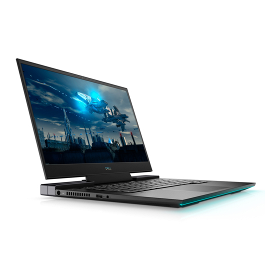
G7 15 7500
Service manual
Dell G7 15 7500 Service Manual
Hide thumbs
1
2
Table Of Contents
3
4
5
6
7
8
9
10
11
12
13
14
15
16
17
18
19
20
21
22
23
24
25
26
27
28
29
30
31
32
33
34
35
36
37
38
39
40
41
42
43
44
45
46
47
48
49
50
51
52
53
54
55
56
57
58
59
60
61
62
63
64
65
66
67
68
69
70
71
72
73
74
75
76
77
78
79
80
81
82
83
84
85
86
87
88
page
of
88
Go
/
88
Contents
Table of Contents
Troubleshooting
Bookmarks
Table of Contents
Table of Contents
Chapter 1: Working Inside Your Computer
Before Working Inside Your Computer
Safety Instructions
Electrostatic Discharge-ESD Protection
ESD Field Service Kit
Transporting Sensitive Components
After Working Inside Your Computer
Chapter 2: Removing and Installing Components
Recommended Tools
Screw List
Base Cover
Removing the Base Cover
Installing the Base Cover
Battery
Lithium-Ion Battery Precautions
Removing the Battery
Installing the Battery
Coin-Cell Battery
Removing the Coin-Cell Battery
Installing the Coin-Cell Battery
Rear Cover
Removing the Rear Cover
Installing the Rear Cover
Rear-Cover Bracket
Removing the Rear-Cover Bracket
Installing the Rear-Cover Bracket
Display Assembly
Removing the Display Assembly
Installing the Display Assembly
Wireless Card
Removing the Wireless Card
Installing the Wireless Card
Solid-State Drive
Removing the M.2 2230 Solid-State Drive
Installing the M.2 2230 Solid-State Drive
Removing the M.2 2280 Solid-State Drive
Installing the M.2 2280 Solid-State Drive
Memory Modules
Removing the Memory Modules
Installing the Memory Modules
Processor Fan
Removing the Processor Fan
Installing the Processor Fan
Graphics-Card Fan
Removing the Graphics-Card Fan
Installing the Graphics-Card Fan
Power-Adapter Port
Installing the Power-Adapter Port
Removing the Power-Adapter Port
Power Button with Optional Fingerprint Reader
Removing the Power Button with Optional Fingerprint Reader
Installing the Power-Button Board with Optional Fingerprint Reader
Light Bar
Removing the Light Bar
Installing the Light Bar
I/O Board
Removing the I/O Board
Installing the I/O Board
Heat Sink
Removing the Heat Sink
Installing the Heat Sink
G Key
Removing the G Key
Installing the G Key
System Board
Removing the System Board
Installing the System Board
Speakers
Removing the Speakers
Installing the Speakers
Touchpad
Removing the Touchpad
Installing the Touchpad
Keyboard
Removing the Keyboard
Folding the Keyboard Cable
Installing the Keyboard
Palmrest
Removing the Palmrest
Installing the Palmrest
Chapter 3: Device Drivers
Intel Chipset Software Installation Utility
Video Drivers
Intel Serial IO Driver
Intel Trusted Execution Engine Interface
Intel Virtual Button Driver
Wireless and Bluetooth Drivers
Chapter 4: System Setup
BIOS Overview
Entering BIOS Setup Program
Navigation Keys
Boot Sequence
One Time Boot Menu
System Setup Options
System and Setup Password
Assigning a System Setup Password
Deleting or Changing an Existing System Setup Password
Clearing CMOS Settings
Clearing BIOS (System Setup) and System Passwords
Chapter 5: Troubleshooting
Supportassist Diagnostics
System Diagnostic Lights
Built-In Self-Test (BIST)
System Board Built-In Self-Test (M-BIST)
Display Panel Power Rail Built-In Self-Test (L-BIST)
Display Panel Built-In Self-Test (LCD-BIST)
Outcome
Flashing BIOS (USB Key)
Flashing the BIOS
Backup Media and Recovery Options
Wifi Power Cycle
Flea Power Release
Chapter 6: Getting Help and Contacting Dell
Advertisement
Quick Links
Download this manual
Dell G7 15 7500
Service Manual
Regulatory Model: P100F
Regulatory Type: P100F001
June 2020
Rev. A00
Table of
Contents
Previous
Page
Next
Page
1
2
3
4
5
Advertisement
Table of Contents
Need help?
Do you have a question about the G7 15 7500 and is the answer not in the manual?
Ask a question
Questions and answers
Related Manuals for Dell G7 15 7500
Laptop Dell Inspiron 15-7559 Service Manual
7000 series (98 pages)
Laptop Dell Inspiron 15-7558 Service Manual
Inspiron 15 7000 series (85 pages)
Laptop Dell Vostro 15-7570 Owner's Manual
(94 pages)
Laptop Dell Inspiron 15 7000 Gaming Service Manual
(142 pages)
Laptop Dell Vostro 15-7580 Owner's Manual
(104 pages)
Laptop Dell XPS 15 7590 Setup And Specifications
(20 pages)
Laptop Dell Vostro 15 7510 Service Manual
(85 pages)
Laptop Dell Vostro 15 7510 Setup And Specifications
(23 pages)
Laptop Dell Inspirion 15-7568 Quick Start Manual
(11 pages)
Laptop Dell Inspiron 15 7000 Service Manual
(79 pages)
Laptop Dell Inspiron 15-7560 Setup And Specifications
(21 pages)
Laptop Dell 15-7567 Setup And Specifications
(23 pages)
Laptop Dell Inspiron 15-7579 Service Manual
(142 pages)
Laptop Dell Inspiron 15-7572 Setup And Specifications
(26 pages)
Laptop Dell Inspiron 15-7569 Setup And Specifications
(23 pages)
Laptop Dell Inspiron 15-7557 Service Manual
(93 pages)
This manual is also suitable for:
P100f
Table of Contents
Save PDF
Print
Rename the bookmark
Delete bookmark?
Delete from my manuals?
Login
Sign In
OR
Sign in with Facebook
Sign in with Google
Upload manual
Upload from disk
Upload from URL


Need help?
Do you have a question about the G7 15 7500 and is the answer not in the manual?
Questions and answers