
Related Manuals for KBR F144-MS-1V1C6-6RO-6DO-3


Summary of Contents for KBR F144-MS-1V1C6-6RO-6DO-3
- Page 1 User manual Technical Parameters 4-quadrant controller multicomp F144-MS-1V1C6-6RO-6DO-3 System English...
-
Page 2: Table Of Contents
Measuring voltage connection Ph-N..................18 Measuring voltage connection Ph-Ph .................19 KBR Kompensationsanlagenbau GmbH does not accept any liability for any loss or damage resulting from printing errors in or changes to this manual. In addition, KBR Kompensationsanlagenbau GmbH does not accept any liability for any loss or damage caused by defective devices or devices manipulated by the user. - Page 3 Table of contents Commissioning the System .....................20 General Notes on Commissioning ..................20 Navigation and Device Displays .....................22 Device Displays of the Main Menus ..................24 Description of the Individual Display Windows ...............26 9.1. Initialization window: .........................26 Commissioning window if no stage power is programmed........26 9.3.
-
Page 4: Introduction
Introduction Introduction Thank you for choosing this KBR quality product. To become familiar with the operation and programming of the device and to use the full range of functions of this high-quality product at all times, you should read this user manual carefully. - Page 5 Introduction Safety keys This manual contains instructions that you must follow for your personal safety and to avoid material damage. These instructions are identified by a warning sign or information symbol, depending on the degree of hazard they warn about. DANGEROUS VOLTAGE „Warning“...
-
Page 6: Safety Notes
Introduction Safety notes In order to prevent operating errors, device operation is kept as simple as possible. This will enable you to start your device up quickly. It is in your own interest to read the following safety instructions carefully. The applicable DIN/VDE regulations must be observed for installation! Power supply connection, setup and operation of the device must be performed by qualified personnel only. -
Page 7: Product Liability
Each device undergoes a long-term test before delivery. With regard to product liability, please see our general terms and conditions for electron- ic devices, which you can read at www.kbr.de. The warranty on device characteristics only applies if the device is operated in accor-... -
Page 8: Functional Principle Of The Controller
Functional principle Functional Principle of the Controller The multicomp F144-1V1C6DO6RO- 3 hybrid controller has 12 outputs to control capac- itive compensation stages. Outputs 1 to 6 are designed to control thyristor modules (by optocoupler outputs) and outputs 7 to 12 to control capacitor contactors (by floating relay contacts). - Page 9 Functional principle tive power compensation system and causes the fan to be switched on if a predefined temperature threshold is exceeded and switched off again when the temperature drops below the reset temperature. To prevent the fan from switching unnecessarily often, it has a run-on time of 30 minutes. You can switch the fan (relay output 12) on or off permanently using the "Stage status"...
-
Page 10: Control And Display Panel
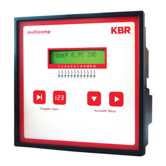
Control and display panel Control and Display Panel multicomp F144-3 hybrid 6RO-6DO Operating elements: 1 LCD displaying the current status and user prompts 2 Number of possible controller output lines 3 Two sensor buttons for parameter configuration 4 Two sensor buttons for menu selection V2.01... - Page 11 Control and display panel General notes on operating the sensor buttons: button Start configuration and reset input button Change values during configuration button Navigate through submenus X button Navigate through main menus and save button during configuration Button combinations: buttons Delete accumulated values and reset the system Default controller settings after reset: Consumption target cos phi: 0.95 inductive...
- Page 12 Control and display panel Stage switching mode: Automatic Sampling rate: Automatic Harmonics monitoring: Activated by set limit Limit THD: Stage power: Not set Max. stage pow. per switch. cycle 0 kVar Thyristor discharge time: 20 ms Contactor discharge time: 180 sec. Password: No password (9999, meaning all functions are accessible)
- Page 13 Control and display panel The controls in the compensation systems are preset. The following parameters need to be checked or set: Target cos phi in accordance with the electricity supplier regulations (for kVA tariff cos phi = 1) Primary current and secondary current in accordance with input current transformer. Voltage transformer ratio, if required NOTE Upon delivery, the bus protocol is set to:...
-
Page 14: Setting Range Of The Configurable Parameters
Setting ranges Setting Range of the Configurable Parameters: Stage state: Stage switching mode Automatic, Manual off, Manual on Commissioning: Password 4 digits, numerical, no password = 9999 (meaning all functions are accessible) Primary current 1 A to 999999 A Secondary current 1 and 5 A Consumption target cosφ... - Page 15 Setting ranges Error message dialog: No measuring voltage The settings Message or No stage power Alarm relay or Message and Facility too small Alarm relay or Off THD too high is identical for all errors! Operating cycle limit exceeded No measuring current Light load Temperature switch-off Extras:...
-
Page 16: Installation And Electrical Connection Of The System
Installation and electrical connection of the system Installation and Electrical Connection of the System General, very important information Tighten all screws and connections. Failure to do so will void the warranty. Install and operate the device in accordance with the applicable VDE regulations (in particular VDE 0100) and the electricity supplier's regulations. -
Page 17: Standard Connection Diagram
Installation and electrical connection of the system Standard connection diagram NOTE The stage outputs 1 to 6 are optocoupler outputs. External voltage supply Terminal input 40 max. 30 VDC (rated voltage 24 VDC), max. 35 mA. When connecting the phase (L1) to terminal 1 and the neutral conductor (N) to terminal 2 (Ph-N 100V –... -
Page 18: Measuring Voltage Connection Ph-N
Installation and electrical connection of the system Measuring voltage connection Ph-N V2.01... -
Page 19: Measuring Voltage Connection Ph-Ph
Installation and electrical connection of the system Measuring voltage connection Ph-Ph V2.01... -
Page 20: Commissioning The System
Commissioning Commissioning the System General Notes on Commissioning Compensation unit with controller The controller is configured as a compensation system component (see connection dia- gram) by default. The following settings need to be configured or checked: Target cos phi according to electricity supplier specifications. Primary and secondary current in the main circuit according to the transformer fitted. - Page 21 Commissioning If a capacitive value is displayed, or if the "G" symbol is flashing, the phase allocation of the current and voltage measurement is incorrect. In the Commissioning programming menu, the phase allocation can be changed using the functions Rot. field U and Rot. field I (provided that there is no generator in operation at the time).
-
Page 22: Navigation And Device Displays
Navigation and device displays Navigation and Device Displays Init First time commissioning Initialisation additional Start menu Stage state Service Commissioning main menus Inst. Cosphi next next next Stage state Start menu Auto / Off / On Service Commissioning Commissioning Stage 01 Stage 01 Enter password Stage 01... - Page 23 Navigation and device displays Start menu Extras Switching performance Error message menu next next next Language Extras Switching performance Switching performance Error message menu Temperature Hysteresis No measuring Display language Attenuation U measurement voltage (selection) connection on / off Extras Extras Switching performance Switching performance...
-
Page 24: Device Displays Of The Main Menus
Displays of the main menus Device Displays of the Main Menus The following main menus and submenus can be used for current displays and controller configuration: Initialization window – no input possible multicomp 06 Hy Initialization Start menu window - display of current values cos... - Page 25 Displays of the main menus Switching performance window – influencing switching performance Switching perfor mance next Error message menu – editing the error message dialog Message next Extras window – setting special parameters Extras next V2.01...
-
Page 26: Description Of The Individual Display Windows
This menu is used for initial startup of the controller, where all necessary settings can be made. If a controller already integrated into a KBR compensation unit by default should be used, only the parameters of the current transformer have to be configured. - Page 27 Description of the display window Password protection (parameter protection): A password (a 4-digit numerical code, e.g. 4321) can be used to protect a system against unauthorized access to the configured parameters. If the password should get lost, the controller can be unlocked with the master password 1976.
- Page 28 NOTE A voltage transformer must be used here with no phase shift between current and volt- age, as the device is not able to compensate this. Setting the discharge time: Checking or, if necessary, changing the discharge time of the capacitor stages is a very important menu item.
- Page 29 menu parameters have been set correctly. To activate learning mode, press , change the setting to Yes by pressing , then press to confirm. The auto configuration then automatically sets the stage powers and discharge times, but these values need to be checked once the learning process has been completed to ensure that they are correct.
-
Page 30: Start Menu Window
Description of the display window 9.3. Start menu window: Example: F144-3 hybrid cos 0.71 IND AAAA This is displayed after the initialization window if the stage power has already been programmed. The current total controller state and the currently measured CosPhi are measured here. - Page 31 Description of the display window NOTE It is similar for the alarm relay or fan relay status display. Explanation: the error message is active, the relay is open (there is an error) the error message is not active, the relay is closed (there is no error) the fan relay is active (the relay is closed, the fan turn-on threshold was or is exceeded or the run-ontime has not elapsed yet) the fan relay is not active (the relay is open, the fan turn-on threshold is not...
-
Page 32: Stage State Window
Description of the display window Stage state window: Stage state next Press to select submenus. The submenus in this window display whether or not the capacitor stages connected are working in automatic mode, or if they are switched on or off permanently. The individual capacitor stages can be selected by pressing You can change the stage state from Auto (Automatic) to Off (switched off perma- nently) or On (switched on permanently) by pressing... -
Page 33: Service Window
Description of the display window Service window: Service next Press to select submenus. The number of connections of each individual capacitor stage is displayed in the sub- menus of this window. This value can be erased individually for each level by pressing together. -
Page 34: Commissioning Window
Description of the display window Commissioning window: Commissioning next Press to select submenus. A step-by-step description of the setup process is given in the submenus of this window. For systems which are already running, the parameters configured during setup can be read out here. - Page 35 Description of the display window Setting target cosine: You can ask your electricity supplier for the target cos, which should be set up at this point. By default, the target cos is set to 0.95 inductive (see the "Default settings" chap- ter).
- Page 36 Description of the display window Configuring the capacitor stages: There are two ways of configuring the capacitor stages. The stages can be configured manually or using the auto configuration mode. It is important to set the stage power correctly. You can find the stage power on the nameplate of the stage or the circuit diagram and then program it manually.
-
Page 37: Switching Performance Window
Description of the display window Switching performance window: Switching performance next Press to select submenus. The default switching performance settings (default settings) are displayed in the sub- menus of this window. These settings apply to most compensation systems. NOTE Check all parameters to ensure that they do not deviate from the specifications for this system. - Page 38 Description of the display window Switching interval (default setting for thyristor stages 50 msec, setting range 50 to 9999 ms, for contactor stages 8 sec, setting range 0 to 10 sec): This value defines the time the controller is idle between two switching operations. Alarm cos phi (default setting ind.
-
Page 39: Error Message Window
Description of the display window Error message window: Message menu next Press to select submenus. The possible messages and the display configuration are displayed in the submenus of this window. The following error messages can be configured: Alarm submenu Possible actions ... -
Page 40: Extras Window
Description of the display window Extras window: Extras next Press to select submenus. The additional possible settings are displayed in the submenus of this window,: If a submenu is selected (by pressing ), the settings can be changed by pressing start entering values, to change the setting and to save it. - Page 41 Description of the display window Reset: The Reset menu item offers various methods of resetting the programmed controller parameters. The programmable parameters are reset to the default settings. This has the advantage that all configured parameters are deleted at the same time and the controller restarts with the default settings.
- Page 42 Description of the display window Contrast setting: The contrast settings of the LCD can be changed in this submenu. Setting range: 0 to 10. Brightness setting: The LCD brightness can be changed in this submenu. Setting range: 0 to 9. Dimmer brightness: ...
- Page 43 Description of the display window Bus mode: In this submenu, the bus protocol of the device can be set. to KBR eBus or Modbus RTU. If Modbus RTU is selected, you can set the transmission parameters now. The supported transmission parameters are: Baud rate (Baud) 4800, 9600, 19200, 38400 ...
-
Page 44: Notes On Troubleshooting
Troubleshooting Notes on Troubleshooting Undercompensation, not enough stages are switched on: Check controller for error messages If the target cos φ is set to 0.8 capacitive, the capac- itors need to start being switched on. If the system is not over-dimensioned, almost all stages need to be switched on. -
Page 45: System And Safety Device Maintenance
Maintenance System and Safety Device Maintenance In order to ensure that your system functions properly and has a long service life, per- form the following checks after commissioning and then on an annual basis. Check and re-tighten all connections. Screw connections may become loose at the ... -
Page 46: Technical Data
Technical Data Technical Data 12.1 Measuring and display values Voltage RMS value of a Phase - 0 or phase - phase, depending on measuring interval configuration Units V, kV;] display switches automatically Display range 0.00 kV to 99.9 kV Measuring range 30 - 690 VAC (max. -
Page 47: Measuring Accuracy
Technical Data 12.2 Measuring accuracy Current ± 0.5% / ± 1 digit (for 0.1 to 5 A) Voltage ± 0.5% / ± 1 digit Power ± 1% / ± 1 digit Power factor ± 1% / ± 1 digit Frequency ±... -
Page 48: Hardware Inputs And Outputs
Technical Data 12.7 Hardware inputs and outputs 12.7.1 Hardware inputs Voltage or U 30 - 690 VAC (max. permissible value: 790 PH-N PH-PH measuring VAC) input Input impedance 1500 kOhm Measuring range 1 measuring range, measuring voltage transformer can be programmed Current or IL2 or I... -
Page 49: Electrical Connection
Technical Data 12.8 Electrical connection Connection elements Plug-in terminals Permissible cross-section 2.5 mm of the connection lines Measurement Fuse max. 1 A slow blow or max. C2 - automatic voltage inputs in addition isolating switch UL/IEC-approved Measuring Fuse NONE!!! Always short-circuit current trans- current input former terminals k and l before opening the circuit! - Page 50 System operation 12.9 Mechanical data Switchboard Housing dimensions 144 x 144 x 60 mm (H x W x D), installation Installation cut-out 138 x 138 mm Weight Approx. 650g 11.10 Standards and miscellaneous Ambient con- Standards DIN EN 60721-3-3:1995-09 + ditions DIN EN 60721-3-3/A2:1997-07; 3K5+3Z11; (IEC721-3-3;3K5+3Z11) Operating tempera- K55/ -5 °C ….
-
Page 51: Selection Of Cables And Fuses
System operation Selection of Cables and Fuses C power (400 V) Q Current consump- Supply cable Fuse (slow-blow) (kvar) tion Cu (mm²) 3 x I (A) I (A) per phase 0.72 1.44 2.16 2.88 3.60 4.32 5.76 7.20 8.64 10.80 14.40 12.5 18.00... -
Page 52: Data Point Description For The Modbus Protocol
Data point description for the Modbus protocol Data point description for the Modbus protocol multicomp F144-3-1Ph 14.1 Modbus commands supported 14.2 Data formats 14.3 Interface parameters 14.4 Device settings 14.5 Data points 14.6 Device information V2.01... -
Page 53: Modbus Commands Supported
Data point description for the Modbus protocol 14.1 Modbus commands supported 0x04 Read Input Registers 0x2B Read Device Identification The multicomp F144-3 does not support broadcast commands. All Modbus commands described are device-specific commands. 14.2 Data formats (unsigned) short: 0x1234 Address Contents 0x12... - Page 54 Data point description for the Modbus protocol Example 1: -12.5 decimal = 0xC1480000 hex M: 24 bit-mantissa E: Exponent with offset of 127 S: Sign for mantissa (S=1 neg.; S=0 pos.) Address Format SEEEEEEE EMMMMMMM MMMMMMMM MMMMMMMM Binary 1 1 0 0 0 0 0 1 0 1 0 0 1 0 0 0 0 0 0 0 0 0 0 0 0 0 0 0 0 0 0 0...
- Page 55 Data point description for the Modbus protocol Example 2: -12.55155 decimal = 0xC148D325 hex Address Format SEEEEEEE EMMMMMMM MMMMMMMM MMMMMMMM Binary 1 1 0 0 0 0 0 1 0 1 0 0 1 0 0 0 1 1 0 1 0 0 1 1 0 0 1 0 0 1 0 1 Example 3: 45.354 decimal = 0x42356A7F hex Address...
-
Page 56: Interface Parameters
Data point description for the Modbus protocol 14.3 Interface parameters Baud rate (baud) Parity Data bits Stop bits 4800,9600,19200, even, odd, none 2 for parity none 38400 otherwise 1 The maximum data length of a Modbus transmission is 256 bytes. This results in a user data length of 253 bytes. - Page 57 Data point description for the Modbus protocol Address Words Description Value Format 0xD020 Byte sequence for float on the Modbus unsigned (1=as defined // 0=reversed) long 0xD022 Frequency correction (0=Auto // 1=50 unsigned Hz // 2=60 Hz) long 0xD024 Stage monitoring (0=No, 1=Yes) unsigned long 0xD026...
- Page 58 Data point description for the Modbus protocol Address Words Description Value Format 0xD04E Thyristor switching interval [ms] 50-9999 unsigned long 0xD050 max. switching capacity per pulse(kvar) 0-9999 unsigned long 0xD052 Attenuation coefficient for voltage unsigned long 0xD054 Attenuation coefficient for current unsigned long 0xD056...
- Page 59 Data point description for the Modbus protocol Address Words Description Value Format Stage parameters 0xD080 Base index for the following stage 0 (= stage 1) unsigned parameters long (addresses 0xD080 to 0xD08E) 0xD082 Mode 0 = Off // 1 = unsigned Auto 2 = On long...
- Page 60 Data point description for the Modbus protocol Address Words Description Value Format 0xD0C0 Base index for the following stage 4 (= stage 5) unsigned parameters long (addresses 0xD0C0 to 0xD0CE) 0xD0CE unsigned long 0xD0D0 Base index for the following stage 5 (= stage 6) unsigned parameters...
- Page 61 Data point description for the Modbus protocol Address Words Description Value Format 0xD11E unsigned long 0xD120 Base index for the following stage 10 (= stage 11) unsigned parameters long (addresses 0xD120 to 0xD12E) 0xD12E unsigned long 0xD130 Base index for the following stage 11 (= stage 12) unsigned parameters...
-
Page 62: Data Points
Data point description for the Modbus protocol 14.5 Data points Data points can be read via the command 0x04 (read input registers) in accordance with table 1. Address Words Description Unit Format 0x0002 Voltage float 0x0004 Current float 0x0006 Network frequency float 0x0008 Current CosPhi... - Page 63 Data point description for the Modbus protocol Messages: Bit 00 set: No stage power (display) Bit 01 set: System temperature switch-off Bit 02 set: No measuring current Bit 03 set: No measuring voltage Bit 04 set: Light load operation Bit 05 set: Voltage harmonics limit reached Bit 06 set: Operating cycle limit reached...
- Page 64 Data point description for the Modbus protocol Example Modbus RTU Request: 01 04 00 01 00 06 21 C8 in which Device address Command 00 01 Read voltage from register 0x0002 (in accordance with Modbus definition, the required address must be set to -1 in the request telex) 00 06 Read 6 registers, i.e.
-
Page 65: Device Information
Data point description for the Modbus protocol Device information The device information is read via the command 0x2B (Read device identification). Information about the manufacturer, device code and device version is read in the pro- cess. The device supplies the “Basic Device Identification”. “Regular”... - Page 66 No further information follows (no additional telex required) Next object ID Number of objects Object ID 00 Text length of ID 00 4B 42 52 20 47 6D 62 48 “KBR GmbH” Object ID 01 Text length of ID 01 6D 75 6C 74 69 63 6F "multicomp F144-3"...
- Page 67 Notes V2.01...
- Page 68 KBR Kompensationsanlagenbau GmbH Am Kiefernschlag 7 T +49 (0) 9122 6373 - 0 www.kbr.de D-91126 Schwabach F +49 (0) 9122 6373 - 83 Germany E info @ kbr.de...
Need help?
Do you have a question about the F144-MS-1V1C6-6RO-6DO-3 and is the answer not in the manual?
Questions and answers