Table of Contents
Advertisement
Quick Links
Advertisement
Table of Contents

Related Manuals for KBR multicomp F144-3PH


Summary of Contents for KBR multicomp F144-3PH
- Page 1 User Manual Technical Parameters multicomp F144-3PH System English...
-
Page 2: Table Of Contents
Description of functions of the multicomp F144-3PH . . . . . . . . . . . . . . . . 8... - Page 3 Technical data multicomp F144-3PH . . . . . . . . . . . . . . . . . .
-
Page 4: Introduction
. User manual This user manual describes the device version multicomp F144-3PH . This user manual must be accessible to the user at all times (e .g . in the switchgear cabinet) . Even if the device is resold to third parties, the manual remains an inherent part of the device . - Page 5 Introduction Safety keys This manual contains instructions that you must follow for your personal safety and to avoid material damage . These instructions are identified by a warning sign or information symbol, depending on the degree of hazard they warn about . DANGEROUS VOLTAGE "Warning"...
-
Page 6: Safety Notes
Introduction Safety notes In order to prevent operating errors, device operation is kept as simple as possible . This will enable you to start your device up quickly . It is in your own interest to read the following safety instructions carefully . The applicable DIN/VDE regulations must be observed during installation! Power supply connection, setup and operation of the device must be performed by qualified personnel only . -
Page 7: Disposal
Each device undergoes a long-term test before delivery . With regard to product liability, please see our general terms and conditions for electron- ic devices, which you can read at www .kbr .de . The warranty on device characteristics only applies if the device is operated in accor-... -
Page 8: Description Of Functions Of The Multicomp F144-3Ph
By using an additional digital input, it is possible to activate a second deviating target CosPhi . Furthermore, the device is equipped with a RS485 bus interface for operation at the KBR eBus with the visual energy computer software . This enables comfortable visualization of the measuring values and the controller's operating state as well as convenient configu- ration of the device via the primary control unit . - Page 9 Please also observe the following notes on start-up and operation: In case of operation in a 3-wire network, a zero-point creator is required (e .g . 700/100 V AC, primary 3-phase connection, available from KBR), as the controller needs a neutral conductor for trouble-free operation .
- Page 10 Installation NOTE A phase-phase measurement (2 measuring phases without neutral conductor) is not possible with this device . NOTE For mixed operation of contactor stages and thyristor stages of the same size, the thyris- tor stages should be assigned to the stages in the back, as the front stages are switched first .
-
Page 11: Connecting The Multicomp
Connection Connecting the multicomp Installation and assembly The applicable VDE regulations must be observed during installation! Before the device is connected to the power supply, check whether the local power supply conditions comply with the specifications on the nameplate . Incorrect connec- tion may result in the destruction of the device . - Page 12 Connection Safety device Voltage and disconnector Terminal 1 Terminal 2 to Terminal 2 Power supply unit US1 required Neutral Phase 100V - 240V +/-10% AC conductor 50/60 Hz Phase Phase 100V - 240V +/-10% AC 50/60 Hz 100V - 240V +/-10% DC V2.00...
-
Page 13: Current Transformer Connection
Connection Current transformer connection: When mounting the transformer, observe the direction of the current or energy flow . If the current transformer is mounted the wrong way, the measured current value will be negative . A prerequisite for this is that energy is supplied to the device . The following points must be observed when connecting the device: Direction of the energy flow ... -
Page 14: Connection Diagram
Connection Connection diagram Strom ussrichtung / current direction Trenn- vorrichtung/ circuit breaker L3 N Netz* Messstrom Messspannung Power Measuring current Measuring voltage Hinweis beachten! read information! 39 70 71 90 91 92 Temperaturfühler ϑ temperature probe cosphi 2 Lüfter Alarm alarm 41 42 43 44 45 46 K2 K3 K4 K5 K6... -
Page 15: Terminal Assignment
Connection Terminal assignment Terminal: Power supply connection 1 (L) and 2 (N): A control voltage is required to supply the device with pow- er . The unit is equipped with a multi-range power supply and may be supplied by voltages 100V – 240V+/ -10% 50Hz/60 Hz (see nameplate for device voltage) . - Page 16 A temperature sensor, e .g . PT1000, can be connected to this input to measure the switchgear cabinet temperature . Temperature measuring range from -10°C to +60°C . 90 (ground) Interface connection 91 (A) For KBR-eBus or Modbus communication . 92 (B): V2.00...
-
Page 17: Default Controller Settings (Default Setting)
Connection Default controller settings (default setting): Methods of measurement 3-phase Commissioning: Measuring voltage transformer Primary voltage 400 V Ph-Ph Secondary voltage 400 V Ph-Ph Zero-point creator Main current transformer Primary current 1000 A Secondary current 5 A Rot .field I 0°... - Page 18 Connection Basic system parameters switching performance: Hysteresis connection 100% of lowest stage power Hysteresis switch-off 100% of lowest stage power Alarm delay 1200 seconds (20 minutes) Idle time: 10 seconds Switching interval: 8 seconds Current attenuation coefficient: Voltage attenuation coefficient: Attenuation coefficient Qmiss: Basic system temperature parameters: Measurement...
- Page 19 Control and display panel Miscellaneous: Sampling rate Automatic Error message dialog In case of any errors, message and alarm relay Service: Password No password (9999, meaning all functions are accessible) NOTE LCD parameters, sampling rate, password, bus parameters and language settings are unaffected by reset .
-
Page 20: Control And Display Panel
Control and display panel Control and display panel Display 9 10 11 12 13 14 15 16 17 18 navigation panel A A A A A A A A A A A A A A A A A A cos Ó actual 0.64 cosÓ... -
Page 21: Description Of General Settings
Commissioning Description of general settings: Attenuation (DC) Reduction of the display fluctuations, the measuring cycle of the controller is not influenced . Idle time (t idle) Starts at compensation . After the idle time has expired, the next switching operation follows . -
Page 22: Commissioning Guideline For The Multicomp F144 -3-3Ph
. Controller preconfigured: If you wish to use a controller that is already integrated into a KBR compensation system by default, only the parameters of the current transformer need to be configured . 1. Configuring current transformer values All current transformer parameters need to be configured correctly for the compensation controller to function properly . - Page 23 Commissioning 2. Function test A function test should be performed after all values have been programmed step by step, by disconnecting the controller from the power supply for a few seconds . The controller should start automatically after it is reconnected to the power supply . When reading out the CosPhi voltage in the cosPhi instantaneous menu immediately after switching on, CosPhi should be low and inductive .
-
Page 24: Basic Device Configuration
Commissioning 4. Function test A function test should be performed after all values have been programmed step by step, by disconnecting the controller from the power supply for a few seconds . The controller should start automatically after it is reconnected to the power supply . When reading out the CosPhi voltage in the cosPhi instantaneous menu immediately after switching on, CosPhi should be low and inductive . -
Page 25: Setting Transformer Ratio
Commissioning Setting transformer ratio After pressing the buttons, the following is displayed in the hot key area: Menu description curr. transformer ENTER Display hot-key area Return for configuration Menu selection Menu selection Return After pressing the button, the following appears in the hot-key area of the display: Display hot-key area ... - Page 26 Menu If the setting was changed, the following appears in the hot-key area of the display: Display hot-key area Enter value Continue to next digit Saving the last changes Leave setting menu without saving V2.00...
-
Page 27: Operating Diagram
Menu Operating Diagram main menu sub menu act.missing comp.power target cos phi act. cos phi target L1, L2, L3 act. cos phi max. Q act.missing comp.power miss power frequency voltage L1, L2, L3 L1, L2, L3 U / I cos phi voltage L1, L2, L3 L1, L2, L3... -
Page 28: Menu Structure
/ reset extra display / language KBR eBus LCD parameter measurement scanmode language commissioning bus adress settings runtime system messages settings... - Page 29 Menu switching hyst. switch on hysteresis ( % ) switch o hysteresis ( % ) switch. perform. switching hysteresis switching times switching times damping coe . damping coe . rest period voltage error mess. delay current switching delay react. pwr. miss. temperature parameters overtemp.
-
Page 30: Main Menu Cos Φ
Menu Main menu cos φ First menu line 9 10 11 12 13 14 15 16 17 18 Second menu line A A A A A A A A A A A A A A A A A A Third menu line cos Ó... - Page 31 Menu Display as example: Main menu: = cosφ actual (instantaneous) Stage mode: = all stages automatic on Menu description: = cosφ actual (instantaneous) Measured cosφ: = 0 .64 inductive Missing compensation power: = 22 .4 kvar twice, you can display the maximum value of the missing By pressing the button compensation power .
-
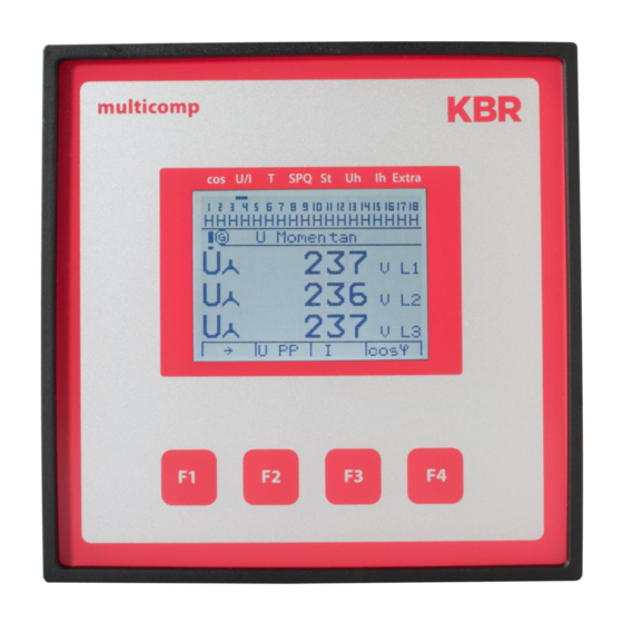
Page 32: Main Menu Voltage / Current
Menu Main menu Voltage / Current 9 10 11 12 13 14 15 16 17 18 A A A A A A A A A A A A A A A A A A U Actual UÇ V L1 UÇ V L2 UÇ... -
Page 33: Main Menu Temperature
Menu Main menu Temperature 9 10 11 12 13 14 15 16 17 18 A A A A A A A A A A A A A A A A A A Temperature 28.7 °C ® oTemp Menu description Temperature oTemp Display hot-key area Display of overtemperature switch-offs Scroll through main menu... -
Page 34: Main Menu Power
Menu Main menu power 9 10 11 12 13 14 15 16 17 18 A A A A A A A A A A A A A A A A A A Apparent power S L1 14.1 S L2 14.4 S L3 11.9 ®... -
Page 35: Main Menu Stages
Menu Main menu stages 9 10 11 12 13 14 15 16 17 18 A A A A A A A A A A A A A A A A A A Stage 01 10.0 kvar 3-Ph s type ... -
Page 36: Main Menu Uh Voltage Harmonics
Menu 5.10 Main menu Uh voltage harmonics 9 10 11 12 13 14 15 16 17 18 A A A A A A A A A A A A A A A A A A harm. U act 0.80 0.64 0.48 0.32 0.16... -
Page 37: Sub Menu Thd Voltage
Menu 5.11 Sub menu THD voltage 9 10 11 12 13 14 15 16 17 18 A A A A A A A A A A A A A A A A A A harm. U THD 1:13 AM 1:02 AM 1:20 AM ¡... -
Page 38: Main Menu Ih Current Harmonics
Menu 5.12 Main menu Ih current harmonics 9 10 11 12 13 14 15 16 17 18 A A A A A A A A A A A A A A A A A A harm. I Inst 0.80 0.64 0.64 0.32 0.16... -
Page 39: Sub Menu Id Current
Menu 5.13 Sub menu ID current 9 10 11 12 13 14 15 16 17 18 A A A A A A A A A A A A A A A A A A harm. I Id 12:41 AM A Id 12:43 AM A Id 12:39 AM A Id ¡... -
Page 40: Main Menu Extras
Menu 5.14 Main menu Extras 9 10 11 12 13 14 15 16 17 18 A A A A A A A A A A A A A A A A A A Extra measurement commissioning settings messages ® ¯... -
Page 41: Description Of Submenus
Menu 5.15 Description of submenus The Methods of measurement submenu contains the following items: 1. Single-phase measurement 2. 3-phase measurement 5.15.1 The Commissioning submenu contains the following items: Transformer settings (voltage, current): Voltage transformer primary voltage Secondary voltage Zero-point creator Sampling rate Main current transformer Primary current... - Page 42 System operation These transducer adaptors (zero-point creator) are suitable for creating a virtual low-im- pedance neutral point for the device in a three-phase network without neutral conductor . NOTE In the 700 V variant, this also serves to adapt the measuring voltage to the device . Make sure that the device is configured for the operation with a zero-point creator .
-
Page 43: 5.15.2 The Settings Submenu Contains The Following Items
System operation 4. Max. switching capacity Setting ranges: max . switching capacity per switching 0 to 999999 kvar operation NOTE The setting capacitive or inductive stage is indicated by the or symbol . alarm cosphi is not used for compensation systems with inductive switching stages . 5.15.2 The Settings submenu contains the following items: 1. - Page 44 System operation 3. System Basic parameters Switching hyster- Connection switching perfor- esis: Disconnection mance Switch mode Switching times: Idle time Alarm delay Switching interval Attenuation Voltage coefficients: Current Qmiss Temperature Activate measure- Switching on fan parameters ment Switching off fan Switching thresh- Switching on system olds:...
- Page 45 System operation NOTE Stage selection mode (switching mode): The priority of switching criteria for compensation stages can be changed in the menu Extra ==> Settings => System => Basic Parameters => Switching Performance => Switch- ing Hysteresis => Switching Mode . The aim of the switching criteria is to use the compensation stages as evenly as possible .
- Page 46 System operation NOTE In Priority 1 under menu item stages (St), instead of the operating cycle, the operating hours (turn-on duration) of the compensation stage are displayed . 9 10 11 12 13 14 15 16 17 18 A A A A A A A A A A A A A A A A A A Stage 01 ...
-
Page 47: Reset Of Parameters: Reset To Default Settings (Delivery State)
System operation 5.15.3 Reset of parameters: Reset to default settings (delivery state) Setting ranges: Hysteresis connection 70 to 150% Hysteresis switch-off 70 to 150% Idle time 0 to 999 .99 sec . Alarm delay for FTS 1 to 9999 sec . Switching interval 10 ms to 999 .99 sec . - Page 48 System operation The default settings are: Switching threshold fan = 28°C / hysteresis = 5°C Switching threshold alarm = 45°C / hysteresis = 5°C Switching threshold overtemperature = 48°C / hysteresis = 5°C This means that the fan switches on when 28°C is exceeded and switches off again when the temperature drops below 23°C .
- Page 49 System operation 5.15.4 The Messages submenu contains the following items: Active error messages Error state Error messages No stage power Power failure Reset performed Temperature switch-off No measuring current No measuring voltage Light load operation LIM Harmon U LIM Harmon I LIM Operating cycle LIM Operating cycle LIM Average current value...
-
Page 50: Notes On Troubleshooting
System operation Notes on Troubleshooting: Undercompensation, not enough stages are switched on. Check controller for error messages If the target cos phi is set to 0 .8 capacitive, the capac- itors need to start to be switched on . If the system is not over-dimensioned, almost all stages need to be switched on . -
Page 51: System And Safety Device Maintenance
System operation System and Safety Device Maintenance In order to ensure that your system functions properly and has a long service life, perform the following checks after commissioning and then on an annual basis . Check and re-tighten all connections . Screwed connections may become loose at the ... -
Page 52: Technical Data Multicomp F144-3Ph
System operation 8 Technical data multicomp F144-3PH Measuring and display values Voltage Units [V, kV;] display switches automatically Display range 0 V to 999 kV Measuring range 3-phase 25 … 230 … 280 VAC, 50 / 60 Hz Current Units [A;kA] display is switched... -
Page 53: Measuring Accuracy
System operation Measuring accuracy Current ± 1 % / ± 1 digit Voltage ± 1 % / ± 1 digit Power ± 2 % / ± 1 digit Power factor ± 2 % / ± 1 digit Frequency ± 0 .1 Hz / ± 1 digit Measuring principle Sampling 128 readings per period... -
Page 54: Hardware Inputs And Outputs
250V (AC) / 2A floating sation stage relay Serial interface RS 485 for connection to the KBR eBus; a connection maximum of 32 devices per bus segment, up to 1000 m without bus repeater if placed accordingly . For additional information see installation guide KBR eBus . -
Page 55: Electrical Connection
UL/IEC-ap- proved Relay output Fuse max 2 A medium time-lag Connection of Connection material For proper operation, use shielded twist- KBR eBus ed-pair cables only, e .g . I-Y(St)Y 2x2x0 .8 Transformer Connections See connection diagram connection Mechanical data Switchboard... -
Page 56: Standards And Miscellaneous
System operation Standards and miscellaneous Environ- Standards DIN EN 60721-3-3:1995-09 + mental DIN EN 60721-3-3/A2:1997-07; 3K5+3Z11; conditions (IEC721-3-3;3K5+3Z11) Operating -5°C … +55°C temperature Air humidity 5% … 95%, non-condensing Storage temperature -25°C … +70°C Operating height up to max . 2000 m above sea level Electrical Standards DIN EN 61010-1:2011-07;... - Page 57 Notes V2.00...
- Page 58 Notes V2.00...
- Page 59 Notes V2.00...
- Page 60 KBR Kompensationsanlagenbau GmbH Am Kiefernschlag 7 T +49 (0) 9122 6373 - 0 www.kbr.de D-91126 Schwabach F +49 (0) 9122 6373 - 83 Germany E info @ kbr.de...
Need help?
Do you have a question about the multicomp F144-3PH and is the answer not in the manual?
Questions and answers