
Related Manuals for KBR F144-MS-1V1C1TI6DO-3


Summary of Contents for KBR F144-MS-1V1C1TI6DO-3
- Page 1 Technical reference 4-quadrant controller multicomp F144-MS-1V1C1TI6DO-3 F144-MS-1V1C1TI12DO-3 Your partner for network analysis System English...
- Page 2 KBR multicomp F144-3 6DO/12DO © KBR Kompensationsanlagenbau GmbH Misprints, printing errors and technical changes reserved...
-
Page 3: Table Of Contents
Table of contents KBR multicomp F144-3 6DO/12DO Functional principle Error message window: ....39 of the controller ........8 Extras window: ........40 Control and display panel ..... 10 Notes on troubleshooting .... 44 Setting range of the System and safety configurable parameters: .... - Page 4 Introduction Dear customer Thank you for choosing a KBR product. To familiarize yourself with operation and configuration of the device, we recommend that you read this manual carefully. This will enable you to make use of the entire range of functions that this high-quality product offers.
- Page 5 Introduction KBR multicomp F144-3 6DO/12DO These operating instructions contain notes that must be observed for your personal safety and to avoid damage to equipment. These instructions are identifi ed by a warning sign or information symbol, depending on the degree of hazard they represent.
- Page 6 KBR multicomp F144-3 6DO/12DO Introduction Safety notes In order to prevent operating errors, handling of the device has been kept as simple as possible. This will enable you to use the device very quickly. In your own interests, however, we recommend you read the following safety instruc- tions carefully.
- Page 7 Introduction KBR multicomp F144-3 6DO/12DO Product liability You have purchased a high-quality product. We only use components of the highest quality and maximum reliability. Each device is subjected to long-term testing before it is delivered. For details on product liability, please refer to our general terms and conditions for electronic equipment.
-
Page 8: Functional Principle Of The Controller
KBR multicomp F144-3 6DO/12DO Functional principle Functional principle of the controller The controller's microprocessor records the mains voltage and current con- sumption of the entire plant by measuring transformer inputs (A/D converter) and, on the basis of this, calculates the active and reactive power ratio of the power supply. - Page 9 Functional principle KBR multicomp F144-3 6DO/12DO The settings are saved on an EEPROM so that they are not lost in the event of a power failure. The measuring cycle of the controller used to record the necessary network parameters takes approx. 20 ms.
-
Page 10: Control And Display Panel
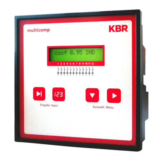
KBR multicomp F144-3 6DO/12DO Control and display panel Control and display panel multicomp F144-MS-1V1C1TI6DO-3 multicomp F144-MS-1V1C1TI12DO-3 Operating elements: 1 LCD displaying the current status and user prompts 2 Number of possible controller output lines 3 Two sensor buttons for parameter configuration 4 Two sensor buttons for menu selection Rev. - Page 11 Control and display panel KBR multicomp F144-3 6DO/12DO General notes on operating the sensor buttons: button Start configuration and reset input button Change values during configuration button Navigate through submenus button Navigate through main menus and save button during configuration...
- Page 12 KBR multicomp F144-3 6DO/12DO Control and display panel Stage power: Not set Max. stage power per switching cycle: 0 kvar Stage power monitored: Deactivated Discharge time: 20 ms Password: No password (9999, meaning all functions ...
- Page 13 Control and display panel KBR multicomp F144-3 6DO/12DO The controls in the compensation systems are preset. The following parameters need to be checked or set: Target cos phi in accordance with the electricity supplier regulations (for kVA tariff cos phi = 1) Primary current and secondary current in accordance with input current ...
-
Page 14: Setting Range Of The Configurable Parameters
KBR multicomp F144-3 6DO/12DO Control and display panel Setting range of the configurable parameters: Stage state: Stage switching mode Automatic, Manual off, Manual on Commissioning: Password 4 digits, numerical, no password = 9999 (meaning all functions are accessible) Primary current... - Page 15 Control and display panel KBR multicomp F144-3 6DO/12DO Error message dialog: Missing measuring voltage The setting Message or Missing stage power Alarm relay or Message and PFC too small Alarm relay or Off THD too high is identical for all errors!
-
Page 16: Installation And Electrical Connection Of The System
KBR multicomp F144-3 6DO/12DO Installation and electrical connection Installation and electrical connection of the system General, very important information Tighten all screws and connections. Failure to do so will void the warranty. Install and operate the device in accordance with the applicable VDE regula- ... -
Page 17: Current Transformer Connection And Measuring Voltage
Installation and electrical connection KBR multicomp F144-3 6DO/12DO Current transformer connection and measuring voltage If possible, mount the transformer in the phase that corresponds to L1 of the compensation system (determine by means of voltage measurement). All ca- pacitor and consumer currents must be determined. In case of an unbalanced phase load (in small companies), install the transformer in the phase with the highest load. - Page 18 KBR multicomp F144-3 6DO/12DO Installation and electrical connection Connection measuring voltage Ph-N Rev. 1.00...
- Page 19 Installation and electrical connection KBR multicomp F144-3 6DO/12DO Connection measuring voltage Ph-Ph Rev. 1.00...
-
Page 20: Commissioning The System
KBR multicomp F144-3 6DO/12DO Commissioning the system General notes on commissioning The controller is confi gured as a compensation system component (see con- nection diagram) by default. The following settings need to be confi gured or checked: Target cos phi according to the energy supplier's specifi cations. - Page 21 KBR multicomp F144-3 6DO/12DO The first switching operation may take up to 10 seconds. The stages are switched in set intervals until compensation occurs. The displayed cos phi must increase to at least the set target cos phi. Rev. 1.00...
-
Page 22: Navigation And Device Displays
KBR multicomp F144-3 6DO/12DO Navigation and device displays Navigation and device displays Init First time commissioning Initialisation Commissioning Start menu Service Stage state weitere Menüs Inst. Cosphi next next next Stage state Auto / Off / On Start menu Service... - Page 23 Navigation and device displays KBR multicomp F144-3 6DO/12DO Start menu Switching performance Error message menu Extras next next next Language Extras Switching performance Switching performance Error message menu Temperature meas. Hysteresis Display language Attenuation U No meas. voltage on / off...
-
Page 24: Device Displays Of The Main Menus
KBR multicomp F144-3 6DO/12DO Displays of the main menus Device displays of the main menus Different main menus and submenus can be used for current displays and controller configuration. Initialization menu – no input possible multicomp F144-3 6-stage or 12-stage... - Page 25 Displays of the main menus KBR multicomp F144-3 6DO/12DO Service window – display and deletion options Service next Commissioning window – operating parameter entry Commissioning next Switching performance window – influencing switching performance Switch. perform. next Error message menu – editing the error message dialog Message menu next ...
-
Page 26: Description Of The Individual Display Windows
This menu is used for initial startup of the controller, where all necessary set- tings can be made. If you wish to use a controller that is already integrated into a KBR compensa- tion system by default, only the parameters of the current transformer need to be confi gured. - Page 27 Description of the display window KBR multicomp F144-3 6DO/12DO Password protection: A password (a 4-digit numerical code, e.g. 4321) can be used to protect a sys- tem against unauthorized access to the configured parameters. If the password should get lost, the controller can be unlocked with the master password 1976.
- Page 28 KBR multicomp F144-3 6DO/12DO Description of the display window Setting the discharge time: Checking or, if necessary, changing the discharge time of the capacitor stages is a very important menu item. Please make sure that the correct value is set,...
-
Page 29: Start Menu Window
Description of the display window KBR multicomp F144-3 6DO/12DO The controller should start automatically after it is reconnected to the power supply. If the cosφ voltage is read in the start menu immediately after switching it on, the value for cosφ should be low and inductive. The controller then starts to switch on the individual capacitor stages. - Page 30 KBR multicomp F144-3 6DO/12DO Description of the display window The current readings are displayed in the submenus: Measuring voltage in volts depending on the selected connection type (Com- missioning menu, Rot. field U submenu) in Ph-N (5) or Ph-Ph (ˉ).
-
Page 31: Stage State Window
Description of the display window KBR multicomp F144-3 6DO/12DO Stage state window: Stage state next Press to select submenus. The submenus in this window display whether or not the capacitor stages connected are working in automatic mode, or if they are switched on or off permanently. -
Page 32: Service Window
KBR multicomp F144-3 6DO/12DO Description of the display window Service window: Service next Press to select submenus. The number of connections of each individual capacitor stage is displayed in the submenus of this window. You can delete the accumulated operating cycles for all stages by selecting Delete operating cycles and pressing simultaneously. -
Page 33: Commissioning Window
Description of the display window KBR multicomp F144-3 6DO/12DO Commissioning window: Commissioning next Press to select submenus. A step-by-step description of the setup process is given in the submenus of this window. For systems which are already running, the parameters configured during setup can be read out here. - Page 34 KBR multicomp F144-3 6DO/12DO Description of the display window CAUTION! Changing the main current transformer parameters or voltage transformer values subsequently can directly infl uence the capacitor stages for which the stage power was determined using the auto confi guration mode. This ensures that the stage power is adequately adjusted in case of a subsequent correction of the transformer parameters.
- Page 35 Description of the display window KBR multicomp F144-3 6DO/12DO The same applies for deactivation in case of overcompensation. If the stage power limit is set lower than the value of the largest existing stage, but larger than "0", the controller automatically uses the largest capacitor stage available.
- Page 36 KBR multicomp F144-3 6DO/12DO Description of the display window If you want to activate learning mode, make sure that all previous submenu parameters have been confi gured correctly. To activate learning mode, press U, change the setting to es by pressing V, then press X to confi rm.
-
Page 37: Switching Performance Window
Description of the display window KBR multicomp F144-3 6DO/12DO Switching performance window: Switch. perform. next Press to select submenus. The default switching performance settings (default settings) are displayed in the submenus of this window. These settings apply to most compensation systems. - Page 38 KBR multicomp F144-3 6DO/12DO Description of the display window Switching interval (default setting 50 ms, setting range 50 to 9999 ms): This value defi nes the time the controller is idle between two switching opera- tions. Alarm cos phi (default setting ind. 0.92, setting range ind. 0.70 to 1.0): This ...
-
Page 39: Error Message Window
Description of the display window KBR multicomp F144-3 6DO/12DO Error message window: Message menu next Press to select submenus. The possible messages and the display configuration are displayed in the sub- menus of this window. The following error messages can be configured:... -
Page 40: Extras Window
KBR multicomp F144-3 6DO/12DO Description of the display window NOTE The stage monitoring function (see Extras menu, Stage power monitored submenu) does not generate any messages, but marks the stages with an X (in the Start menu window). Extras window: Extras next ... - Page 41 Description of the display window KBR multicomp F144-3 6DO/12DO Sampling rate: The power frequency tracing settings are displayed in this submenu. If the setting is "Auto", the sampling rate is tracked automatically in a range from 40 to 70 Hz. Alternatively, a fi xed sampling rate of 50 Hz or 60 Hz can be set.
- Page 42 KBR multicomp F144-3 6DO/12DO Description of the display window Dimmer brightness: The LCD dimming can be changed in this submenu. Setting range: 0 to 9. The brightness is reduced after a set time of 15 minutes. Light load limit: ...
- Page 43 In this submenu, the bus protocol of the device can be set. to KBR eBus or Modbus RTU. The KBR eBus setting is used for testing purposes. If Modbus RTU is selected, you can set the transmission parameters here. The...
-
Page 44: Notes On Troubleshooting
KBR multicomp F144-3 6DO/12DO Troubleshooting Notes on troubleshooting Undercompensation, not enough stages are switched on: Check controller for error messages If the target cos φ is set to 0.8 capacitive, the capacitors need to start being switched on. If the system is not over-dimen- sioned, almost all stages need to be switched on. -
Page 45: System And Safety Device Maintenance
Maintenance, security KBR multicomp F144-3 6DO/12DO System and safety device maintenance In order to ensure that your system functions properly and has a long service life, perform the following checks after commissioning and then on an annu- al basis. Check and re-tighten all connections. Screw connections may become loose ... -
Page 46: Technical Data
KBR multicomp F144-3 6DO/12DO Technical data 11.1 Measuring and display values Voltage RMS value of a Phase - 0 or phase - phase, depending on measuring interval configuration Units [V; kV;] display is switched automatically Display range 0.00 kV to 99.9 kV Measuring range 30 - 690 VAC (max. -
Page 47: Measuring Accuracy
KBR multicomp F144-3 6DO/12DO 11.2 Measuring accuracy Current ± 0.5% / ± 1 digit (for 0.1 to 5 A) Voltage ± 0.5% / ± 1 digit Power ± 1% / ± 1 digit Power factor ± 1% / ± 1 digit Frequency ±... -
Page 48: Hardware Inputs And Outputs
KBR multicomp F144-3 6DO/12DO Technical data 11.7 Hardware inputs and outputs 11.7.1 Hardware inputs Voltage or U 30 - 690 VAC (max. permissible value: 790 PH-NPH-N PH-PH measuring VAC) input Input impedance 750 kOhm Measuring range 1 measuring range, measuring voltage transformer is configu-... -
Page 49: Electrical Connection
Technical data KBR multicomp F144-3 6DO/12DO 11.8 Electrical connection Connection elements Plug-in terminals Permissible cross-section 2.5 mm of the connection lines Measurement Fuse protection max. 6 A voltage inputs Measuring Fuse protection NONE!!! Always short-circuit current trans- current input former terminals k and l before opening the... -
Page 50: Mechanical Data
KBR multicomp F144-3 6DO/12DO Technical data 11.9 Mechanical data Switchboard Housing dimensions 144 x 144 x 60 mm (H x W x D), installation Installation cut-out 138 x 138 mm Weight Approx. 650 g 11.10 Standards and miscellaneous Ambient con-... -
Page 51: Selection Of Cables And Fuses
Technical data KBR multicomp F144-3 6DO/12DO Selection of cables and fuses C power (400 V) Q Current consumption Supply cable Fuse (slow-blow) (kvar) I (A) per phase Cu (mm²) 3 x I (A) 0.72 1.44 2.16 2.88 3.60 4.32 5.76 7.20... -
Page 52: Data Point Description For The Modbus Protocol
KBR multicomp F144-3 6DO/12DO Data point description for the Modbus protocol multicomp F144-3 13.1 Modbus commands supported 13.2 Data formats 13.3 Interface parameters 13.4 Device settings 13.5 Data points 13.6 Device information Rev. 1.00... -
Page 53: Modbus Commands Supported
KBR multicomp F144-3 6DO/12DO 13.1 Modbus commands supported 0x04 Read input registers 0x2B Read device identification The multicomp F144-3 does not support broadcast commands. All Modbus commands described are device-specific commands. 13.2 Data formats (unsigned) short: 0x1234 Address Contents 0x12... - Page 54 KBR multicomp F144-3 6DO/12DO Example 1: -12.5 decimal = 0xC1480000 hex M: 24 bit-mantissa E: Exponent with offset of 127 S: Sign for mantissa (S=1 neg.; S=0 pos.) Address Format SEEEEEEE EMMMMMMM MMMMMMMM MMMMMMMM Binary 1 1 0 0 0 0 0 1...
- Page 55 KBR multicomp F144-3 6DO/12DO Example 2: -12.55155 decimal = 0xC148D325 hex Address Format SEEEEEEE EMMMMMMM MMMMMMMM MMMMMMMM Binary 1 1 0 0 0 0 0 1 0 1 0 0 1 0 0 0 1 1 0 1 0 0 1 1 0 0 1 0 0 1 0 1 Example 3: 45.354 decimal = 0x42356A7F hex...
-
Page 56: Interface Parameters
KBR multicomp F144-3 6DO/12DO 13.3 Interface parameters Baud rate (baud) Parity Data bits Stop bits 4800,9600,19200, even, odd, none 2 for parity none 38400 otherwise 1 The maximum data length of a Modbus transmission is 256 bytes. This results in a user data length of 253 bytes. - Page 57 KBR multicomp F144-3 6DO/12DO Address Words Description Value Format 0xD020 Byte sequence for float on the Modbus unsigned (1=as defined // 0=reversed) long 0xD022 Frequency correction (0=Auto // 1=50 unsigned Hz // 2=60 Hz) long 0xD024 Stage monitoring (0=No, 1=Yes)
- Page 58 KBR multicomp F144-3 6DO/12DO Address Words Description Value Format 0xD04E unsigned long 0xD050 max. switching capacity per pulse 0-9999 unsigned long 0xD052 Attenuation coefficient for voltage unsigned long 0xD054 Attenuation coefficient for current unsigned long 0xD056 Attenuation coefficient Q unsigned...
- Page 59 KBR multicomp F144-3 6DO/12DO Address Words Description Value Format 0xD07E Stage parameters 0xD080 Base index for the following stage 0 (= stage 1) unsigned parameters long (addresses 0xD080 to 0xD08E) 0xD082 Mode 0 = Off // 1 = unsigned Auto 2 = On...
- Page 60 KBR multicomp F144-3 6DO/12DO Address Words Description Value Format 0xD0C0 Base index for the following stage 4 (= stage 5) unsigned parameters long (addresses 0xD0C0 to 0xD0CE) 0xD0CE unsigned long 0xD0D0 Base index for the following stage 5 (= stage 6)
- Page 61 KBR multicomp F144-3 6DO/12DO Address Words Description Value Format 0xD11E unsigned long 0xD120 Base index for the following stage 10 (= stage 11) unsigned parameters long (addresses 0xD120 to 0xD12E) 0xD12E unsigned long 0xD130 Base index for the following stage...
-
Page 62: Data Points
KBR multicomp F144-3 6DO/12DO 13.5 Data points Address Words Description Units Format 0x0002 Voltage float 0x0004 Current float 0x0006 Network frequency float 0x0008 Current CosPhi float 0x000a Active power float 0x000c Fundamental reactive power float 0x000e No compensation power float... - Page 63 KBR multicomp F144-3 6DO/12DO Messages: Bit 00 set: No stage power (display) Bit 01 set: System temperature switch-off Bit 02 set: No measuring current Bit 03 set: No measuring voltage Bit 04 set: Light load operation Bit 05 set: Voltage harmonics limit reached...
- Page 64 KBR multicomp F144-3 6DO/12DO Example Modbus RTU Request: 01 04 00 1F 00 32 40 19 where Device address Command 00 01 Read voltage from register 0x0002 (in accordance with Modbus definition, the required address must be set to -1 in...
-
Page 65: Device Information
KBR multicomp F144-3 6DO/12DO xx xx xx xx Voltage 13 harmonic xx % xx xx xx xx Maximum missing compensation power xx var xx xx xx xx Relay states (12 bit: bit 0 = stage 1 - bit 11 =... - Page 66 KBR multicomp F144-3 6DO/12DO Device address Command MEI type (see Modbus definition) "Basic identification" (see Modbus definition) "Conformity level" (see Modbus definition) No further information follows (no additional telex required) Next object ID Number of objects Object ID 00 Length of the text of ID 00 4B 42 52 20 47 6D 62 "KBR GmbH"...
- Page 67 Notes KBR multicomp F144-3 6DO/12DO Rev. 1.00...
- Page 68 KBR Kompensationsanlagenbau GmbH www.kbr.de Am Kiefernschlag 7 T +49 (0) 9122 6373 - 0 D-91126 Schwabach F +49 (0) 9122 6373 - 83 Germany El info @ kbr.de...
Need help?
Do you have a question about the F144-MS-1V1C1TI6DO-3 and is the answer not in the manual?
Questions and answers