
Related Manuals for KBR multimax D6-5 Series


Summary of Contents for KBR multimax D6-5 Series
- Page 1 User Manual Technical Parameters multimax D6-xxx-5 You can find the instructions for your KBR System English device at our download center. https://www.kbr.de/de/dienstleistungen/ download-center...
-
Page 2: Table Of Contents
Error Messages ........................15 2.12 Long-term Memory ......................15 KBR Kompensationsanlagenbau GmbH does not accept any liability for any loss or damage resulting from printing errors in or changes to this manual. In addition, KBR Kompensationsanlagenbau GmbH does not accept any liability for any loss or damage caused by defective devices or devices manipulated by the user. - Page 3 Table of Contents Device Overview ........................16 Installation ..........................17 Device Assembly ........................17 Connection Diagram ......................18 Terminal Assignment ......................19 Device Memory ........................20 Control and Display Panel ....................21 Description of Buttons and Displays, Default Settings, Setting Ranges ....21 Error Message Overview: ....................29 Overview of system parameters ..................31 Description of parameters ....................31 9.0.1 General parameters ......................31...
- Page 4 Table of Contents 12.1.7 Mechanical data and dimensioned drawing of the basic module ......75 12.1.8 Surrounding conditions / electrical safety ..............76 12.1.9 Troubleshooting ........................76 12.2 General Technical Data for Additional Modules ............78 12.3 Serial interface ........................80 12.4 Protective Measures – Overvoltage and Lightning Protection ......80 Connecting additional modules ..................81 13.1.
- Page 5 Table of Contents 13.6.3 Function of Scan button ....................103 13.6.4 DIP Switch Functions: ......................104 13.6.5 Technical Data: ........................105 V5.00...
-
Page 6: Introduction
Introduction Introduction Thank you for choosing this KBR quality product. To become familiar with the operation and programming of the device and to use the full range of functions of this high-quality product at all times, you should read this user manual carefully. -
Page 7: Safety Keys
Introduction Safety Keys This manual contains instructions that you must follow for your personal safety and to avoid material damage. These instructions are identified by a warning sign or information symbol, depending on the degree of hazard they warn about. DANGEROUS VOLTAGE "Warning"... -
Page 8: Safety Notes
Introduction Safety Notes In order to prevent operating errors, device operation is kept as simple as possible. This will enable you to start your device up quickly. It is in your own interest to read the following safety instructions carefully. DANGEROUS VOLTAGE The applicable DIN/VDE regulations must be observed during installation! Connection to the mains, commissioning and operation of the device may only be carried... -
Page 9: Product Liability
Each device undergoes a long-term test before delivery. With regard to product liability, please see our general terms and conditions for electronic devices, which you can read at www.kbr.de. The warranty on device characteristics only applies if the device is operated in... -
Page 10: Range Of Functions
Range of Functions Range of Functions The multimax D6-xxx-5 energy control system can significantly contribute to lowering commercial energy costs. Monitoring Energy Consumption The peak power is an important cost factor for special tariff devices. The multimax D6-xxx-5 ensures optimum distribution of available power and helps pre- vent expensive power peaks by means of intelligent monitoring of energy consumption. -
Page 11: Digital Output
Range of Functions 2.4.2 Digital Output The basic module of the multimax load management system features a digital output (I/O – parameter M00.12, please ensure correct polarity!) with a freely assignable output address. This means that devices, which feature a digital input (S compatible), can be controlled directly. -
Page 12: Recording States Using Message Modules
Range of Functions Recording States Using Message Modules By determining the state of the optimizable devices, the optimization action can be con- trolled. A message input can be associated to every output. In addition to the digital input module inputs (for floating switches or electronic switches (ensure correct polarity)), the voltage inputs of the multimess D4-xxx-1 measuring module can also be used as message inputs. -
Page 13: Power Measurement Using Energy Pulses From The Energy Supplier
Range of Functions Power Measurement Using Energy Pulses from the Energy Supplier The multimax can be adapted to the energy supplier conditions. Energy proportional en- ergy pulses are required as characteristic quantity for the power. They are either provided by the network operator or created by a pulse generator/counter. The instantaneous power for trend calculation is continuously determined via pulse period measurement and pulse count. -
Page 14: Measurement Period Synchronization Using An Energy Supplier Pulse
Range of Functions Channels 1, 2 and 3 (single channel): If set to single phase, only the measured value of this channel will be relayed as current power. If set to three-phrase, the measured value of the channel is extrapolated to a three-phase measurement and relayed as the total current power. -
Page 15: Error Messages
Range of Functions 2.11 Error Messages If an error occurs, an error message is displayed. Emergency shut-down E17 Pcum > Ptarg Emergency shut-down E18 max. Pact limit violated Emergency shut-down E22 meter pulse 1 failure Emergency shut-down E23 meter pulse 2 failure Emergency shut-down E24 meter pulse 3 failure Emergency shut-down E25 meter pulse 4 failure Emergency shut-down E26 meter pulse 5 failure... -
Page 16: Device Overview
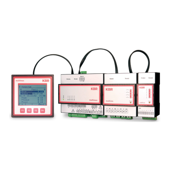
Device Overview Device Overview From left to right, you can see: The display and its function keys multimax D6-xxx-5 basic module, The multisio relay module The multisio digital input module V5.00... -
Page 17: Installation
Installation Installation This chapter describes: „Mounting the device“ „Connection diagram“ on page 18 „Terminal assignment“ on page 19 Device Assembly The housing of the multimax D6-xxx-5 has been designed for switchgear cabinet mount- ing on a 35 mm DIN rail. The module is snapped onto the mounted DIN rail. CAUTION The device control voltage must be secured with a back-up fuse on site. -
Page 18: Connection Diagram
Installation Connection Diagram Relaisausg. Vorwarnkontakt Relaisausgang Linie 4 Relaisausgang Linie 3 Relaisausgang Linie 2 Relaisausgang Linie 1 Schaltspannung Messperioden- Synchroneingang Tarif- Umschalteingang Sollwert- Umschalteingang Zählereingang 2 Zählereingang 1 Digitalausgang V5.00... -
Page 19: Terminal Assignment
Installation Terminal Assignment Terminals 1 (L) / 2 (N) and PE Power Supply Connection. Auxiliary voltage is required for device operation. For technical data, please refer to the nameplate. Terminals 90 (ground), Interface Connection. 91 (A) and 92 (B) For communication at the energy bus Terminal 40 (C) Connection for Voltage Supply to the Relay Out- put Terminals 41 to 45. -
Page 20: Device Memory
Installation Device Memory Non-volatile long-term memory The device is equipped with an internal, non-volatile memory in which long-term data is stored. Buffered real-time clock (RTC) After an uninterrupted charging time (device connected to the supply voltage) of approx. 8 hours, the buffer capacitor will have a sufficient charge to protect the internal clock from failure due to lack of operating voltage for approx. -
Page 21: Control And Display Panel
Control and Display Panel Control and Display Panel multimax 1 Display Navigation Panel P actual Ptarg Pacc Trem. 12:30 12:40:23 12:45 2 Data Display Pact Ptrend Pcorr ® menu 3 Hot Key Area Description of Buttons and Displays, Default Settings, Setting Ranges 1 Display Navigation Panel The navigation panel shows the main menu selected, considerably simplifying device operation. - Page 22 Preprogrammed Defaults V5.00...
- Page 23 Preprogrammed Defaults V5.00...
- Page 24 Parameter Setting Ranges Parameters Setting Ranges General TYPE a value, switching input, list of target values parameters 1 Target value 1 0 to 50000 kW Degree of optimi- 80% to 100% zation Period duration 1, 10, 15, 30 or 60 minutes Switching interval 2 to 30 seconds Synchronization...
- Page 25 Parameter Setting Ranges Prewarning Contact Parameters: TYPE Negative compensation power greater than available switch-off power Cumulated power greater than power warning threshold Trend power greater than power warning threshold Off (function deactivated) Warning threshold 30 to 150 percent Hysteresis 0 to 50000 kW Minimum on time 0 to 999 minutes Minimum down time...
- Page 26 Parameter Setting Ranges Parameters Setting ranges Meter inputs Input 1 +/- I 00 to I 50 Input 2 +/- I 00 to I 50 Input 3 +/- I 00 to I 50 Input 4 +/- I 00 to I 50 Input 5 +/- I 00 to I 50 Meter pulse...
- Page 27 Parameter Setting Ranges Parameters Setting Ranges Bus parameters Bus address 0 to 9999 Bus protocol KBR eBus / Modbus Bus address KBR 0 to 9999 configurable on the device, scan- eBus ning mode Transmission 38,400 baud speed Bus address Modbus 1 to 247 configurable on the device...
- Page 28 Parameter Setting Ranges Error Message Dialog: Parameters Setting Ranges I01 power failure Message, message and error message relay, I02 limit violated Message, message and alarm relay, off I04 synchronized Message, message and alarm relay, off pulse missing I05 reset Message, message and alarm relay, off performed I07 error message Message, message and alarm relay, off...
-
Page 29: Error Message Overview
Error Message Overview Error Message Overview: Global Error State Error no. Explanation Power failure has occurred A limit has been violated External synchronized pulse missing Reset has been performed Error message ( 1 when relay is switched, 0 if not) Error State multimax D6-xxx-5 Error no. - Page 30 Parameter setting ranges Error no. Explanation Module 18 cannot be reached Module 17 cannot be reached Module 16 cannot be reached Module 15 cannot be reached Module 14 cannot be reached Module 13 cannot be reached Module 12 cannot be reached Module 11 cannot be reached Module 10 cannot be reached Module 9 cannot be reached...
-
Page 31: Overview Of System Parameters
Overview of system parameters Overview of system parameters You can program the multimax D6-xxx-5 to adapt it to the system to be optimized. The following are programmed: “General parameters” “Measured value output” “Line parameters” “Clock time / date” ... - Page 32 - Target values 2 and 3 can be activated by customizable inputs Target value list - the internal target value list is processed If, however, the target value is to be provided by an internal or external (via the KBR eBus) timer program, this has priority. V5.00...
- Page 33 Description of parameters NOTE The system can be implemented as a monitor of maximum or minimum values. Gen. Programming Explanation param. 2 Minimum On/Off Monitors the minimum recovery in the case of a monitoring self-generated supply and contractually-agreed energy recovery into the energy supplier network. Pact On/Off Period-independent monitoring of whether current...
- Page 34 Description of parameters Gen. param. 3 Programming Explanation (only when select- ing switch inp. as TYPE in the Gen. param. area 1) Target value 2 Numeric value in Enter the value here that has been agreed kW, MW, m by the energy supplier. Target value 3 Numeric value in Enter the value here that has been agreed...
- Page 35 Description of parameters Maximum prewarning contact: The default contact setting is closed, when active. Prewarning contact parameters: TYPE Selection Negative compensation power greater than available switch-off power Cumulated power greater than power warning threshold Trend power greater than power warning threshold Off (function deactivated) Warning threshold...
- Page 36 Description of parameters Default values: Prewarning contact active TYPE -Pcorr > Pavail Minimum on time in minutes 0.2 minutes (=12 sec.) Minimum off time in minutes 0.2 minutes (=12 sec.) Period time-out in minutes 0 minutes Prewarning contact address A 48 Cannot be changed Default setting function: The contact switches when the compensation power is negative if there is no longer any...
- Page 37 Description of parameters The result is the following: The contact switches if the cumulated power is greater than 90 kW (90% of the target value) and the message I20 prewarning contact active is issued. No hysteresis is available, as the cumulated power only increases during the measure- ment period.
- Page 38 Description of parameters The result is the following: The contact switches if the trend power is greater than 90 kW (90% of the target value) and the message I20 prewarning contact active is issued. The hysteresis for switching back is 10kW, meaning that the contact will switch back if the trend power is 80 kW (90% of the target value minus a hysteresis of 10kW).
-
Page 39: Line Parameters
Line Parameters Line parameters The following assignments have been set for inputs (I) and outputs (O): Inputs: I 00 to I 50 Outputs: O 00 to O 50 Whereby: O 01 to O 32 correspond to lines 1 to 32 (i.e. are permanently assigned to the lines) ... - Page 40 Line parameters 2. Select a line and begin programming with Para and Edit. Para Line Programming Explanation (1, 2, etc.) Power Numeric value inkW, Device power. MW, m Priority Numeric value 1–32 Device shut-down priority. The default setting is the line number. TYPE Standard, therm., Standard, therm.
- Page 41 Line parameters power per channel is extrapolated to a three-phase device. multimess D4-1 I/O parameters channel 4 (mixed channel), 3-phase measurement: Channel name Primary transformer voltage value (taken from channels 1 to 3) Secondary transformer voltage value (taken from channels 1 to 3) ...
- Page 42 Line parameters c) Type A standard device is switched on and off based on its programmed power (taking into account any programmed time-outs). The standard parameters are set for this device type. Parameters (example): Power 18 kW Priority Type Standard on switch-off Open active...
- Page 43 Line parameters Optimization in the continued heating phase Maximum on time 0 minutes Period time-out 0 minutes Lead time 0 seconds Run-on time 0 seconds Minimum on time/day 0 hours Minimum on time 0 minutes Minimum down time 0 minutes Maximum off time 0 minutes Application examples: Optimization in the heat-up phase Optimization in the continued heating...
- Page 44 Line parameters Thermo-switch opens: Main switch input address closed Thermostat switch input address Open (device has reached its temperature) Reason for optimization line switching On/optimization/1 This means that: the device is now in the continued heating phase (after the thermo- stat switch first opens) and could be switched off for optimization reasons.
- Page 45 Line parameters Cyclic operation (no forced cycles ): To set the device cycles, only the times Maximum on time Maximum off time are programmed. These times may not be followed to completion if in the case of max. off => there is already sufficient free power such that no further ...
- Page 46 Line parameters The line output power only changes in the switching cycle: once the output power has changed, it will not be changed again for the duration of the switching cycle. Once output power reaches 0 or 100%, the next line is switched to (depending on the line priority).
- Page 47 Line parameters 3. Program the address with Adr and Edit. Para Lines Programming Explanation (1, 2, ...) Adr. Numeric value Device address, O01–O04 on the base device; output O01–O32, afterwards, numbering is continued for connected fixed modules. Adr. I00-I50 The multimax checks whether the device is on or feedb.
- Page 48 Line parameters Para Lines Programming Explanation (1, 2, ...) Feedback Enable, Defines whether the device is integrated into type Manual_Off, optimization via its feedback (enable), remains Manual_On, constantly on (Manual_On), or is switched off in- Emergency_Off, dependently of its trend calculation (Manual_Off ). Emergency_On, In the case of running timer programs, there is priority 1–32...
-
Page 49: Meter Inputs
Meter inputs 10.1 Meter inputs In the Meter inputs area, you can set and configure inputs for meters. 1. From the main menu, select Meter inputs > Enter. 2. Begin programming by selecting Edit. Meter inputs Programming Explanation Input 1, 2, etc. +/- I... -
Page 50: Module Management
Module Management 10.2 Module Management In the Module Management area, you can manage and program the basic and additional modules. From the main menu, select Module Management > Enter. Select a module. CAUTION: If necessary, start a module scan using Scan. This function recognizes your connected modules;... - Page 51 Module Management E.g. when defining as a pulse counter Para (...) Programming Explanation Input Log. I… Fixed logical address. address inverse On/Off Determines whether the input reacts to a positive or negative pulse. t Pact -> 0 Numeric value in Determines the time before the power drops to 0.
-
Page 52: Timer Programs
Timer programs: 10.4 Timer programs Time programs no EA Action Mode 01 11 linegroup 02 10 switchgrp. 03 10 tariff 04 10 limit Auto 05 10 priority 06 10 targetval Auto ¡ ¯ Para In the timer program overview, the following information is displayed: Number of the timer program ... - Page 53 Timer programs: Setting the parameters: para. time prog para. time prog enabling Prog 1 ID-No start 08:00 16:00 TYPE domain 07:30:00 su MO TU WE TH FR sa action linegroup start 01.01.2013 domain 16:15:00 01.01.2039 act. ¡ EDIT ¡ ® EDIT To start a programmed timer program, Enable must be activated and the time range must have been entered (time, date).
- Page 54 Timer programs: Parameters: Settings: Program name Text input ID no. 1 to 65534 Type Day/week Range start Time, date Range end Time, date Enable Yes/No Start time Time End time Time Select day for type: day/week Sunday to Saturday, individually selectable for type: day Select month for type: day/week January to December, individually select- able...
- Page 55 Timer programs: NOTE The timer programs have a priority order corresponding to their ID no., whereby ID 01 is the most important timer program, then ID 02, etc. When carrying out an action, timer programs (internal or external) always have priority over bus switching, digital input (manual switching) and device programming.
-
Page 56: Time/Date
Clock time/date 10.5 Time/date In the Time/date area, you can set the time and date and configure daylight saving time settings. 1. From the main menu, select Time/date > Enter. 2. Begin programming by selecting Edit. Time/ Programming Explanation date Time Numeric value in Defines the time if this is not provided by an exter-... -
Page 57: Bus Parameters
Bus parameters 10.6 Bus parameters In the Bus parameters area, you can set the address of the KBR eBus, for example. 1. From the main menu, select Bus parameters > Enter. 2. If necessary, start a bus scan using scan. -
Page 58: Display Parameters
Display parameters 10.7 Display parameters In the Display parameters area, you can change the LED display settings. 1. From the main menu, select Display parameters > Enter. 2. Begin programming by selecting Edit. Display Programming Explanation parameters Contrast Numeric value in % Defines the text contrast in relation to the background. -
Page 59: Error Message Parameters
Bus parameters 10.8 Error message parameters In the Error message parameters area, you can set the type of message for different errors. 1. From the main menu, select Error message param. > Enter. 2. Begin programming by selecting Edit. Error message Programming Explanation param. -
Page 60: Password / Reset
Display parameters 10.9 Password / Reset In the Password area, you can define a password to protect the device from unau- thorized inputs and reset the password. Here you can also reset the device to factory settings. 1. From the main menu, select Password > Enter. The device displays “Unlocked, ”... -
Page 61: Description Of Display Items
Description of Display Items Description of display items 11.1 P current Ptarg multimax Cumulative power Unoccupied P actual cycle time Ptarg Pacc Trem. Measuring 12:30 12:40:23 12:45 period start Pact Ptrend Pcorr ® menu Current power Trendleistung (Trend power) Currently in the period Parameters Period (current time) -
Page 62: Potential
Description of display items 11.2 Potential Power values of all devices that can still currently be switched off multimax Lines with this power have already been switched off potential P availab. Lines with this power P shutoff have been switched off P connect. - Page 63 Description of display items Monthly maximum: Max 1: Value, date, time multimax Max 2: Value, date, time maximum of month Max 3: Value, date, time Max1: 441 kW 06.05.2013 13:45 Max2: 214 kW Use the key to display the 02.05.2013 13:45 maximum values from the pre- Max3:...
-
Page 64: Line Data
Description of display items 11.3 Line data Device state due to Reason for switching multimax Device feedback line data Current li sta sw.reas power consumption 01 On disabled - M00.6 02 Off optimis. - M00.7 03 On timeProg - M00.8 î... -
Page 65: I/O State
Description of display items 11.4 I/O state Recording input and Connected/not connected output states Possible messages: multimax i No pulse at pulse input (low level) I/O state I Pulse detected at pulse no. type state input (high level) bas MMax o Output passive 1 4ROIS (relay or pulse) -
Page 66: Tracked Ptarg
Description of display items 11.5 Tracked Ptarg Display of the set target values or the tracked target multimax values, if target value track- ing is activated Ptarg tracked Resets to the configured target val.1 700 kW target value target val.2 300 kW target val.3 500 kW... -
Page 67: Meter Values
Description of display items 11.6 Counter values In the Meter values menu, in addition to the current tariff, multimax the following values can also be displayed: counter values Total values up to now consumpt Continuous energy meter Total HT consumption recovery Continuous energy meter Total LT consumption... - Page 68 Description of display items Use the key to display multimax Monthly values – current month month values Continuous energy meter month Total HT consumption consumpt Continuous energy meter Total LT consumption recovery Continuous energy meter Total HT recovery î ¡ Ø...
- Page 69 Description of display items Use the key to display multimax Daily values day values Continuous energy meter 10.06.2013 Total HT consumption consumt Continuous energy meter Total LT consumption recovery Continuous energy meter Total HT recovery cycle inp ¯Ø dayد Continuous energy meter Total HT recovery Use the...
- Page 70 Description of display items Use the key to display multimax Period values cycle values Period values in Date 10.06.2013 period duration grid consumpt 15:00 Consumption and recovery 14:45 14:30 14:15 14:00 inp îØ ê cyclØ dayØî Use the key to display the period values, starting with the latest. Use the key to display meter inputs meter 1 to meter 5 individually.
-
Page 71: Current Error Messages
Description of display items 11.7 Current error messages Active error messages do not have to be acknowl- multimax edged and disappear when the error is resolved act. error mess. Messages that have to be acknowledged (Del.) e.g. lim. violated, power No violations failure ®... -
Page 72: Technical Data Multimax D6-Xxx-5
Technical Data multimax D6-xxx-5 12.1 Technical data for multimax D6-xxx-5 basic module 12.1.1 Control and display elements Operation Pushbutton for reset and scan mode (accessible after housing cover removal) Control display 6 green LEDs: 5 x input status, 1 x operating status 12.1.2 Device memory Energy, data and program... -
Page 73: Electrical Connection
2.5 mm necting cables Input power Fuse max. 1 A slow blow supply max. C2 automatic isolating switch UL/IEC-approved KBR eBus Connection For proper operation, use shielded twisted-pair and Modbus material cables only, e.g. I-Y(St)Y 2x2x0.8 connection Pulse inputs Connection and... -
Page 74: Hardware Outputs
38.400 baud, can be selected on Modbus 4.800, 9.600, 19.200 baud Address assignment Can be addressed up to address number 9999 for KBR eBus; scan mode can be activated on the device Bus addresses for Modbus 1 to 247 configurable on the device... -
Page 75: Mechanical Data And Dimensioned Drawing Of The Basic Module
12.1.7 Mechanical data and dimensioned drawing of the basic module Top hat Housing dimensions 90 x 106 x 61 mm (H x W x D) rail device Mounting type Wall mounting on DIN rail 7.5 mm deep, in accordance with DIN EN 50022; suitable for distribution board mounting Weight Approx. -
Page 76: Surrounding Conditions / Electrical Safety
Technical Data 12.1.8 Surrounding conditions / electrical safety Surrounding Standards DIN EN 60721-3-3/A2: 1997-07; conditions 3K5+3Z11; (IEC721-3-3; 3K5+3Z11) Operating temperature K55 (-5 °C …. +55 °C) Air humidity 5 % … 95 %, non-condensing Storage temperature K55 (-25°C …. +70°C) Operating height 0…2,000 m above sea level Electrical... - Page 77 Technical Data 12.2.3 Electrical connection Module bus connection Connection material ready-made KBR system ca- ble (6 pole modular cable, unshielded), max. length 30m if placed accordingly 12.2.4 Mechanical data Switchboard installation Housing dimensions 96 x 96 x 46 mm (H x W x D) Installation cut-out 92 x 92 mm...
-
Page 78: General Technical Data For Additional Modules
Connection Modular connector RJ12 6P6C Module bus serial RS485 interface: interface Module bus RJ12 for ready-made KBR system cable, max. connection length 30 m when placed suitably Transmission 38400 Bps speed Bus protocol KBR module bus Mechanical data (for all models except for multisio D4-4RO-ISO-1 and multimess... - Page 79 Mechanical data multisio D6-4RO-ISO-ES-1: DIN rail mea- Housing 90 x 106 x 61 mm (H x W x D) surement dimensions device Mounting type Wall mounting on DIN rail 7.5 mm deep, in accor- dance with DIN EN 50022. Suitable for distribution board mounting Weight Approx.
-
Page 80: Serial Interface
D6-xxx-5 devices together on the KBR eBus across great distances. Typically, the bus is connected to the computer via the KBR eBus TCP gateway. With the according Windows® Software, all bus devices can be parameterized and visual- ized. -
Page 81: Connecting Additional Modules
Connecting additional modules Connecting additional modules You can expand your multimax with the additional modules multisio and multimess. You will find a description of the functions of these devices in the following section. 13.1. Function Description of the Relay Output Module Multisio D4-4RO ISO-1 The multisio D4-4RO ISO-1 hardware supports four floating relay outputs, 5 LEDs and an 8-fold DIP switch. -
Page 82: Relay Output Module Led Display
Connecting additional modules 13.1.2 Relay output module LED display In KBR module bus scanning mode, all four output LEDs flash. In module detection mode, the output LEDs generate a chase light effect. The LEDs represent: LED1 for: Output relay 1 (A1) switched... -
Page 83: Dip Switch Functions
Connecting additional modules 13.1.4 DIP switch functions Mode of operation: For every output, the multisio D4-4RO ISO-1 differentiates between the operating modes “normal” and “manual. ” Switching is performed via the DIP switches 5 to 8. The DIP switches are assigned to the outputs as follows: DIP switch 5 determines the operating mode of output 1 ... -
Page 84: Dip Switch Settings
Connecting additional modules 13.1.5 DIP Switch Settings Mode of State Explanation operation Output 1 = normal operating mode Output 1 = manual operating mode passive / off Output 1 = manual operating mode passive / off Output 2 = normal operating mode Output 2 = manual operating mode passive / off Output 2 = manual operating mode passive / off Output 3 = normal operating mode... -
Page 85: Function Description Of Relay Module Multisio D6-4Ro Iso-1 With Ebus
Connecting additional modules 13.2. Function description of relay module multisio D6-4RO ISO-1 with eBus The multisio D6-4RO ISO-1 with eBus hardware supports four floating relay outputs (changeover relays), 5 LEDs and an 8-fold DIP switch. The relay outputs serve to control contactors of devices or other systems. The module can be accessed from a master device (multimax D6-5, multisio D6-7 or high- er, or a computer with visual energy via multigate ESBS) using the module bus interface. -
Page 86: Connection Variants Of The Supply Voltage
Connecting additional modules NOTE When connecting the phase (L1) to terminal 1 and the neutral conductor (N) to termi- nal 2 (Ph-N 100V – 240V+/-10% DC/50Hz/60Hz) the safety device and the disconnector in the supply line to terminal 2 (N) are not required. The safety device and the disconnector to terminal 2 (N) are only required for the following connection variants: Alternating voltage:... -
Page 87: Terminal Assignment
Connecting additional modules 13.2.3 Terminal Assignment: Terminal 1: Phase (L) and DC (+) Mains Terminal 2: Neutral conductor and DC (-) Terminal PE: Protective earth Terminal 93: eBus ground eBus Terminal 94: eBus A Terminal 95: eBus B Terminal 41: NO contact relay 1 Changeover relay A1: Terminal 45:... -
Page 88: Function Of Scan Button
Connecting additional modules In scanning mode, all 4 output LEDs are flashing. In the module detection mode, the output LEDs generate a chase light effect. The LEDs represent: LED 1: Output relay 1 ( A1 ) switched LED 2: Output relay 2 ( A2 ) switched LED 3: Output relay 3 ( A3 ) switched LED 4:... -
Page 89: Dip Switch For Terminating Rs-485 Interface
Connecting additional modules Output 1 Output 2 Output 3 Output 4 Relay state DIP S1 DIP S5 DIP S2 DIP S6 DIP S3 DIP S7 DIP S4 DIP S8 automatic manual passive / off manual active / on X: DIP switch state does not matter If necessary, the RS-485 interface on the module bus side can be terminated using four DIP switches (terminating resistors are fitted into multisio). -
Page 90: Technical Data
Hardware outputs Module bus Serial interface RS485 interface Module bus connec- RJ12 for ready-made tion KBR system cable, max. length 30 m when suitably placed Maximum DC power output 7W Transmission 38400 Bps speed Bus protocol KBR module bus/eBus optional... - Page 91 Connecting additional modules Continuation of table Hardware Outputs 4 relay outputs 2 plug terminals, each 6-pin Changeover relay A1: Terminal 41 NO contact relay 1 Changeover relay A1: Terminal 45 Shared connection relay 1 Changeover relay A1: Terminal 41 Break contact relay 1 Changeover relay A2: Terminal 42 NO contact relay 2 Changeover relay A2: Terminal 46...
- Page 92 Connecting additional modules 12.2.10 Environmental Conditions / Electrical Safety Surrounding Standards DIN EN 60721-3-3/A2: 1997-07; 3K5+3Z11; conditions (IEC721-3-3; 3K5+3Z11) Operating tem- K55 (-5 °C …. +55 °C) perature Air humidity 5 % … 95 %, non-condensing Storage tempera- K55 (-25°C …. +70°C) ture Operating height 0…2,000 m above sea level Electrical...
-
Page 93: Function Description Of The Digital Input Module Multisio D2-4Di-2
Connecting additional modules 13.3 Function Description of the Digital Input Module Multisio D2- 4DI-2 The multisio D2-4DI-2 hardware is equipped with four digital inputs. The module detects an input as active if the input is shorted out. An open switch is de- tected as passive. -
Page 94: Digital Input Module Led Display
Connecting additional modules 13.3.2 Digital Input Module LED Display In KBR module bus scanning mode, all four input LEDs flash. In module detection mode, the input LEDs generate a chase light. The LEDs represent: LED1 for input 1 LED2 for input 2... -
Page 95: Dip Switch Functions
Connecting additional modules 13.3.4 DIP switch functions Mode of operation: For every input, the multisio D2-4DI-2 differentiates between the operating modes “nor- mal” and “manual. ” Switching is performed via the DIP switches 5 to 8. The DIP switches are assigned to the inputs as follows: DIP switch 5 determines the operating mode of input 1 ... -
Page 96: Dip Switch Settings
Connecting additional modules Manual operating mode In manual operating mode, the state of DIP switches 1 to 4 is further processed, instead of the state of the corresponding input. The DIP switches are assigned to the inputs as follows: DIP switch 1 determines the state of input 1 ... -
Page 97: Function Description For Multimess D4-1 Measurement Module
Connecting additional modules 13.4 Function description for multimess D4-1 measurement module The multimess D4-1 is a multimeter for DIN rail mounting. On the output side, it can measure all typical alternating and direct current parameters of devices. For busbar assembly (7.5 mm rail) ... -
Page 98: Commissioning The Multimess D4-1 With Multimax D6-Xxx-5
Connecting additional modules max. C2 Automat/automat max. 1 A träge/slow-blow Trennvorrichtungen circuit breaker 12 11 10 Modul Modul N L3 L2 L1 Messspannung multimess D4-1 Measuring voltage Messstrom Measuring current k1 l1 k2 l2 k3 l3 20 21 22 23 24 25 Strom ussrichtung / current direction 13.4.2 Commissioning the multimess D4-1 with Multimax D6-xxx-5... -
Page 99: Function Description Of The Digital Input Module Multisio D2-4Ai-2
Connecting additional modules 7. To set the measurement module into scan mode, touch the scan sensor button for about 4 seconds (the green status LED flashes more quickly) 8. The multimax D6-5 basic module now recognizes the measurement module and adds it to the list of connected modules. -
Page 100: Analog Input Module - Led Display
Connecting additional modules 13.5.2 Analog Input Module - LED Display In the KBR eBus scanning mode, all 4 output LEDs flash. In module detection mode, the output LEDs generate a chase light effect. The LEDs represent: LED 1 for output 1 (analog value) -
Page 101: The Individual Dip Switches Signify The Following
Connecting additional modules 13.5.4 The Individual DIP Switches Signify the Following: Switches Channel 1: normal operation Channel 1: test operation Channel 1: 0 V to 10 V Channel 1: 0mA to 20mA (in test operation) (in test operation) Channel 2: normal operation Channel 2: test operation Channel 2: 0 V to 10 V Channel 2: 0mA to 20mA... -
Page 102: Function Description Of The Digital Output Module Multisio D2-4Do-2
Connecting additional modules 13.6 Function Description of the Digital Output Module multisio D2-4DO-2 The multisio D2-4DO-2 hardware supports 4 digital outputs, 5 LEDs and an 8-position DIP switch. At its outputs, the module generates digital pulses as configured via the module bus. For each hardware output, a voltage of up to 35 V has to be applied to the + input. -
Page 103: Digital Output Module - Led Display
Connecting additional modules 13.6.2 Digital Output Module - LED Display In the KBR eBus scanning mode, all 4 output LEDs flash. In module detection mode, the output LEDs generate a chase light effect. A blinking LED indicates that the corresponding digital output has been switched to manual operation. - Page 104 Connecting additional modules 13.6.4 DIP Switch Functions: Manual operation: Each output can manually be set to active. If the DIP switch for the channel is set to “OFF, ” the output state is established within the module. If the DIP switch is set to “ON, ”...
- Page 105 Connecting additional modules 13.6.5 Technical Data: Hardware outputs: Four digital outputs compatible Max. 35 VDC/50 mA Plug-in terminal, 8-pin Display 4x message 1x operation display Control unit DIP switch 1x eightfold, output configuration Button Scan button (module bus) V5.00...
- Page 106 Notes V5.00...
- Page 107 Notes V5.00...
- Page 108 KBR Kompensationsanlagenbau GmbH Am Kiefernschlag 7 T +49 (0) 9122 6373 - 0 www.kbr.de D-91126 Schwabach F +49 (0) 9122 6373 - 83 Germany E info @ kbr.de...
Need help?
Do you have a question about the multimax D6-5 Series and is the answer not in the manual?
Questions and answers