
Related Manuals for KBR multicomp F144-NC-1V1C6DO6RO-2


Summary of Contents for KBR multicomp F144-NC-1V1C6DO6RO-2
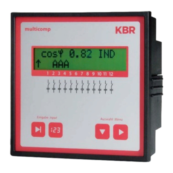
- Page 1 Technical reference 4-quadrant controller multicomp F144-NC-1V1C6DO6RO-2 Your partner for network analysis System English...
- Page 2 KBR multicomp F144-NC-1V1C6DO6RO-2 © KBR Kompensationsanlagenbau GmbH Misprints, printing errors and technical changes reserved...
-
Page 3: Table Of Contents
Table of contents KBR multicomp F144-NC-1V1C6DO6RO-2 Dear customer .............4 Service window: ....... 27 Disclaimer .............5 Commissioning window:....28 Safety notes ............6 Switching performance window: 31 Product liability ...........7 Error message window: ....33 Disposal..............7 Extras window ........34 Functional principle Notes on detecting errors ..... -
Page 4: Dear Customer
Introduction Dear customer We would like to thank you for choosing a KBR product. To familiarize yourself with the device operation and confi guration, we recommend you read this manual carefully. This will enable you to make use of the entire range of functions that this high-quality product off ers. -
Page 5: Disclaimer
Introduction KBR multicomp F144-NC-1V1C6DO6RO-2 These operating instructions contain notes that must be observed for your personal safety and to avoid damage to equipment. These instructions are identifi ed by a warning sign or information symbol, depending on the degree of hazard they represent. -
Page 6: Safety Notes
KBR multicomp F144-NC-1V1C6DO6RO-2 Introduction Safety notes In order to prevent operating errors, handling of the device has been kept as simple as possible. This way, you will be able to use the device very quickly. In your own interest, however, the following safety notes should be read carefully. -
Page 7: Product Liability
Introduction KBR multicomp F144-NC-1V1C6DO6RO-2 Product liability You have purchased a high-quality product. Only components of the highest quality and maximum reliability are used. Each device is subject to long-term testing before it is delivered. For details on product liability, please refer to our general terms and conditions for electronic equipment. -
Page 8: Functional Principle Of The Controller
KBR multicomp F144-NC-1V1C6DO6RO-2 Functional principle Functional principle of the controller The multicomp F144-1V1C6DO6RO-2 hybrid controller has 12 outputs to control capaci- tive compensation stages. Outputs 1 to 6 are designed to control thyristor modules (by optocoupler outputs) and outputs 7 to 12 to control capacitor contactors (by fl oating relay contacts). - Page 9 Functional principle KBR multicomp F144-NC-1V1C6DO6RO-2 switch-off hysteresis can be increased to up to 150% of the lowest stage power. After an adaption time of 60 seconds, the thyristor stages are switched by contactor stages of the same size. This guarantees that the fast control characteristics can be kept.
-
Page 10: Control And Display Panel
KBR multicomp F144-NC-1V1C6DO6RO-2 Control and display panel Note Limit for overvoltage switch-off = rated voltage + 10% (taking into account the measuring voltage ratio). The value of 10% cannot be changed and serves to protect the compensation system. The reset hysteresis is 1 % of the rated volt- age. - Page 11 Control and display panel KBR multicomp F144-NC-1V1C6DO6RO-2 General notes on operating the sensor buttons: Button Start input for confi guration and reset Button Change values during confi guration Button Navigation though submenus Button Navigation through main menus and save button...
- Page 12 KBR multicomp F144-NC-1V1C6DO6RO-2 Control and display panel Extras menu THD limit: Harmonics monitoring: Activated by set limit Contactor stage operating cycle limit: 80000 Operating cycle count: Activated by set limit Scanning frequency: Automatic Stage power monitoring: Deactivated ...
-
Page 13: Installation And Electrical Connection Of The System
Installation and electrical connection KBR multicomp F144-NC-1V1C6DO6RO-2 Installation and electrical connection of the system General, highly important information Tighten all screws and connections as otherwise the warranty will be rendered void. The device must be installed and operated in accordance with the applicable VDE regulations (in particular VDE 0100) and the energy supplier regulations. -
Page 14: Current Transformer Dimensions
KBR multicomp F144-NC-1V1C6DO6RO-2 Installation and electrical connection Current transformer dimensions The current transformer is designed based on the current consumption of the consumers and not the capacitor current. If other measuring devices are con- nected to a transformer in addition to the reactive power controller, the trans- former power needs to be dimensioned accordingly. -
Page 15: Standard Connection Diagram Measuring Voltage Ph-Ph
Installation and electrical connection KBR multicomp F144-NC-1V1C6DO6RO-2 Standard connection diagram measuring voltage Ph-Ph Rev. 1.00... -
Page 16: Starting Up The System
KBR multicomp F144-NC-1V1C6DO6RO-2 Commissioning Starting up the system General notes on starting up Switch on a suffi cient number of inductive consumers (e.g. motors) before switching the compensation system on. A transformer current of at least 15 mA needs to be fl owing in the secondary circuit for the controller to be acti- vated. -
Page 17: Compensation System With Controller
Commissioning KBR multicomp F144-NC-1V1C6DO6RO-2 Compensation system with controller The controller is preset as a component of a compensation system (refer to the connection diagram of the compensation system). The following need to be programmed or checked: Target CosPhi according to energy supplier regulations. -
Page 18: Navigation And Device Displays
KBR multicomp F144-NC-1V1C6DO6RO-2 Navigation and device displays Navigation and device displays init first commissioning initialization period service commissioning start menu stage state additional main menus inst. Cosphi next next next stage state auto / off / on start menu service... - Page 19 Navigation and device displays KBR multicomp F144-NC-1V1C6DO6RO-2 start menu switching performance extras error message menu next next next display language switching performance switching performance error message menu hysteresis no meas. voltage selection attenuation U connection switching performance error message menu...
-
Page 20: Device Displays Of The Main Menus
KBR multicomp F144-NC-1V1C6DO6RO-2 Device displays of the main menus Device displays of the main menus For current displays and controller confi guration, diff erent main menus and their submenus can be used. Initialization menu – no input possible ... - Page 21 Displays of the main menus KBR multicomp F144-NC-1V1C6DO6RO-2 Commissioning window – entry of operating parameters Switching performance window – infl uencing switching performance Error message menu – editing the error message dialog Extras window – setting special parameters ...
-
Page 22: Description Of The Individual Display Windows
This menu is used for the initial startup of the controller, where all necessary settings can be made. If a controller that is already integrated into a KBR compensation system by default should be used, only the parameters of the current transformer have to be confi gured. - Page 23 Description of the display window KBR multicomp F144-NC-1V1C6DO6RO-2 Password protection: To protect a system against unauthorized access of the confi gured parameters, a password can be entered (4-digit number code, e.g. 4321). In case the password gets lost somehow, the controller can be unlocked with the master password 1976.
- Page 24 KBR multicomp F144-NC-1V1C6DO6RO-2 Description of the display window Setting the discharge time: Checking or, if required, changing the discharge time of the capacitor stages is a very important menu item. The discharge time can be set between 20 and 9999 milliseconds for thyristor stages and 0 to 900 seconds for contactor stages.
-
Page 25: Start Menu Window
Description of the display window KBR multicomp F144-NC-1V1C6DO6RO-2 Start menu window: This is displayed after the initialization window when the stage power has already been programmed. Here, the current total controller state and the cur- rently measured CosPhi are measured. -
Page 26: Stage State Window
KBR multicomp F144-NC-1V1C6DO6RO-2 Description of the display window The missing compensation power is displayed up to a maximum value of 9999.9 kvar. If the value exceeds this limit, ----.- kvar is displayed Power frequency in Hertz THD (Harm. U total) in %, decisive for setting the THD limit (Extras menu, THD limit submenu) The fi rmware version of the controller, e.g. -
Page 27: Service Window
Description of the display window KBR multicomp F144-NC-1V1C6DO6RO-2 Service window: Select submenus by pressing In the submenus of this window, the number of connections of each individual capacitor stage is displayed. In the delete operating cycles menu item, you can delete the accumulated operating cycles for all stages. -
Page 28: Commissioning Window
KBR multicomp F144-NC-1V1C6DO6RO-2 Description of the display window Commissioning window: Select submenus by pressing In the submenus of this window, a step-by-step description of the setup pro- cess is given. For systems already in operation, the parameters set during setup can be read out here. - Page 29 Description of the display window KBR multicomp F144-NC-1V1C6DO6RO-2 Note Changing the series transformer parameters later on can directly infl uence the capacitor stages for which the stage power was determined using the auto confi guration mode. This way it is ensured that the stage power is adequately adjusted in case of a subsequent correction of the transformer parameters.
- Page 30 KBR multicomp F144-NC-1V1C6DO6RO-2 Description of the display window If the stage power limit is set lower than the value of the largest existing stage, but larger than or equal to “0”, the controller automatically uses the largest capacitor stage available.
-
Page 31: Switching Performance Window
Description of the display window KBR multicomp F144-NC-1V1C6DO6RO-2 Switching performance window: Select submenus by pressing In the submenus of this window, the settings made for the switching perfor- mance by default are displayed (default settings). These settings apply to most of the compensation systems. - Page 32 KBR multicomp F144-NC-1V1C6DO6RO-2 Description of the display window Idle time (default setting for thyristor stages 20 msec, setting range 20 to 9999 msec, for contactor stages 10 sec, setting range 0 to 300 sec): This value defi nes the time the controller is idle after compensation before another switching operation is performed (connection or disconnection).
-
Page 33: Error Message Window
Description of the display window KBR multicomp F144-NC-1V1C6DO6RO-2 Error message window: Select submenus by pressing In the submenus of this window, the possible messages are displayed, as well as the display confi guration. The following error messages can be confi gured:... -
Page 34: Extras Window
KBR multicomp F144-NC-1V1C6DO6RO-2 Description of the display window Caution If there is a stage monitoring error (cf. Extras menu, Monitoring stage power submenu), no message is displayed, but the stages in the start menu window are marked with an X. - Page 35 Description of the display window KBR multicomp F144-NC-1V1C6DO6RO-2 Sampling rate: In this submenu, the power frequency tracing settings are displayed. The setting "Auto" causes the sampling rate to be traced automatically, within a range of 40 to 70 Hertz. Alternatively, a fi xed sampling rate of 50 Hz or 60 Hz can be set.
-
Page 36: Notes On Detecting Errors
Undercompensation, all stages are switched on: The existing system is not suffi cient (e.g. due to new inductive consumers). Please contact the KBR service (for system expansion). Check the main fuse and group fuses of the system. Checking the controller parameters. -
Page 37: System And Safety Devices Maintenance
Maintenance, security KBR multicomp F144-NC-1V1C6DO6RO-2 System and safety devices maintenance In order to ensure proper function and a long service life of your system, perform the following checks after startup and subsequently once a year. Check and re-tighten all connections. Screw connections may become loose at the beginning due to thermal stress. -
Page 38: Setting Range Of The Confi Gurable Parameters
KBR multicomp F144-NC-1V1C6DO6RO-2 Confi gurable parameters Setting range of the confi gurable parameters: Primary voltage 1 V to 39999 V Ph-Ph Secondary voltage 1 V to 999 V Ph-Ph Primary current 1 A to 39999 A Secondary current 1 and 5 A Rot.fi eld U... - Page 39 Confi gurable parameters KBR multicomp F144-NC-1V1C6DO6RO-2 THD limit 0 to 10% Sampling rate automatic, fi xed 50 Hz, fi xed 60 Hz Password 1111 to 9998, no password 9999, meaning all functions are accessible Display language German, English, French, Spanish...
-
Page 40: Technical Data
KBR multicomp F144-NC-1V1C6DO6RO-2 Technical data Technical data 11.1 Measuring and display values Voltage RMS value of a Phase - 0 or phase - phase, measuring interval depending on programming Units [V; kV;] display is switched automatically Display range 0.00 kV to 99.9 kV Measuring range 30 ... -
Page 41: Measuring Accuracy
Technical data KBR multicomp F144-NC-1V1C6DO6RO-2 11.2 Measuring accuracy Current ± 0.5% / ± 1 digit (for 0.1 to 5 A) Voltage ± 0.5% / ± 1 digit Power ± 1% / ± 1 digit Power factor ± 1% / ± 1 digit Frequency ±... -
Page 42: Hardware Inputs And Outputs
KBR multicomp F144-NC-1V1C6DO6RO-2 Technical data 11.7 Hardware inputs and outputs 11.7.1 Hardware inputs Voltage UPH-N or UPH-PH 30 V... 690 V... 790 V AC measuring Input impedance 750 kOhm input Measuring range 1 measuring range, measuring voltage trans- former can be programmed... -
Page 43: Mechanical Data
Technical data KBR multicomp F144-NC-1V1C6DO6RO-2 11.9 Mechanical data Switchboard Housing dimensions 144 x 144 x 60 mm (H x W x D), installation Assembly cut-out 138 x 138 mm Protection type Front IP51 (with optionally available front door max. IP54), terminals IP20 Weight Approx. -
Page 44: Selection Of Lines And Fuses
KBR multicomp F144-NC-1V1C6DO6RO-2 Technical data Selection of lines and fuses C power (400 V) Q Current consumption Supply line Fuse (slow-blow) (kvar) I (A) per phase Cu (mm²) 3 x I (A) 0.72 1.44 2.16 2.88 3.60 4.32 5.76 7.20 8.64... - Page 45 Notes KBR multicomp F144-NC-1V1C6DO6RO-2 Rev. 1.00...
- Page 46 KBR multicomp F144-NC-1V1C6DO6RO-2 Notes Rev. 1.00...
- Page 47 Notes KBR multicomp F144-NC-1V1C6DO6RO-2 Rev. 1.00...
- Page 48 KBR Kompensationsanlagenbau GmbH Am Kiefernschlag 7 T +49 (0) 9122 6373 - 0 www.kbr.de D-91126 Schwabach, F +49 (0) 9122 6373 - 83 Germany E info@kbr.de...
Need help?
Do you have a question about the multicomp F144-NC-1V1C6DO6RO-2 and is the answer not in the manual?
Questions and answers