Table of Contents
Advertisement
Quick Links
Advertisement
Table of Contents

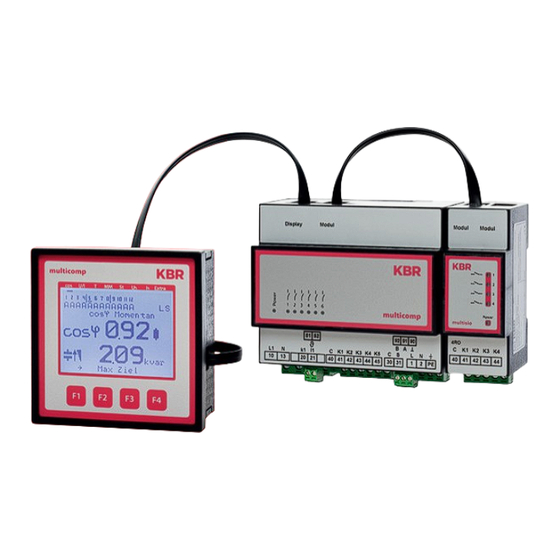
Summary of Contents for KBR multicomp D6 Series
- Page 1 Information Connection and start-up multicomp D6-xxx-7 System English...
- Page 2 Introduction Thank you for choosing this KBR quality product. To familiarize yourself with device operation and configuration, we recommend you read this manual carefully. This will enable you to make use of the entire range of functions that this high-quality product offers.
-
Page 3: Explanation Of Safety Relevant Symbols
Explanation of safety relevant symbols These operating instructions contain notes that must be observed for your personal safety and to avoid damage to equipment. These notes are identified by a warning sign or information symbol, depending on the degree of hazard they represent. DANGEROUS VOLTAGE „Warning“... -
Page 4: Product Liability
Each device is subject to long-term testing before it is delivered. For details on product liability, please refer to our general terms and conditions for elect- ronic equipment, which you can find at www.kbr.de. Warranty device properties apply only if the device has been operated in accordance with its intended use! V7.00... -
Page 5: Overvoltage And Lightning Protection
Disposal Defective, outdated or disused devices must be properly disposed of. If required, we are happy to dispose of the devices for you. Overvoltage and lightning protection It is recommended to install overvoltage protection measures to protect our high-quality devices from damage. We also recommend to protect control voltage inputs and pulse lines, if required. - Page 6 NOTE The following points must be observed when connecting the device: - Energy flow direction - Assignment of measuring voltage input/current transformer input Energy flow direction: When mounting the transformer, observe the current flow or energy flow direction. If the current transformer is mounted the wrong way round, the measured current will be negative.
-
Page 7: Connection Diagram
Connection diagram zu weiteren Busteilnehmern bzw. Leitungsabschluss / Display Modul/ to other bus devices and line termination Module Temperaturfühler / temperature probe multicomp D6-ESBSDS-1V1C6RO-7 K4 K5 44 45 Stufen / Stages Relais / Relay circuit breaker - Trennvorrichtung circuit breaker - Trennvorrichtung * For supply voltage, see type plate * Versorgungsspannung siehe Typenschild max. -
Page 8: Terminal Assignment
Terminal assignment Terminal: 1 (L) and 2 (N): Power supply connection A control voltage is required to supply the device with power. The unit is equipped with a multi-range power supply and may be supplied by voltages of 100 – 240V ± 10% DC 50/60 Hz (see nameplate for device voltage). - Page 9 To begin with, there are two cases in which the start-up procedure for the multicomp D6-xxx-7 differs. Case 1: You have bought a complete compensation system from KBR, and the controller is already installed. If this is the case, certain settings are already preconfigured in the controller.
- Page 10 Controller not preconfigured If an unconfigured controller is to be started up, the following procedure has to be per- formed step by step. 1. Configuring additional modules (multisio D2-1T2RO, multisio D2-4RO, multisio D2-4CI and multimess 14) If there are no additional temperature, relay or induced current measuring modules, this step can be skipped.
-
Page 11: Function Test
4. Configuring the capacitor stages There are two ways of configuring the capacitor stages. The stages can be configured manually or using the auto configuration mode (a connected current measuring module is required). The most important setting to pay attention to is the stage power. The stage power can be looked up on the nameplate of the stage or the circuit diagram and then programmed manually. - Page 12 Controller not configured If a controller already integrated into a KBR compensation unit by default should be used, only the parameters of the current transformer have to be configured. 1. Configuring current transformer values For the compensation controller to function properly, all current transformer parameters have to be set correctly.


Need help?
Do you have a question about the multicomp D6 Series and is the answer not in the manual?
Questions and answers