
Related Manuals for KBR Multicomp 2F144-NC-1V1C06RO


Summary of Contents for KBR Multicomp 2F144-NC-1V1C06RO
- Page 1 Operating instructions Technical parameters 4-quadrant controller multicomp 2F144-NC-1V1C06RO 2F144-NC-1V1C12RO Your network analysis specialist Optimizing Monitoring Optimizing...
- Page 2 KBR GmbH Am Kiefernschlag 7 D-91126 Schwabach T +49 (0) 9122 6373-0 F +49 (0) 9122 6373-83 E info@kbr,de www.kbr.de...
- Page 3 Preface Dear Customer We would like to thank you for choosing a KBR GmbH quality product. In order to familiarize yourself with the operation and programming of the device and always be able to use the whole functionality of this high-quality product, we recommend that you read this manual thoroughly.
- Page 4 The specifications made in this manual are checked on a regular basis, necessary corrections are included in the next revision. We appreciate your corrections and comments. © KBR-GmbH Subject to change Page II von IV...
- Page 5 Safety Precautions General Safety Precautions In order to prevent operating errors, handling of the device is kept as simple as possible. This way, you will be able to use the device very soon. In your own interest, however, you should read the following safety precautions carefully. Warning During installation, the applicable DIN / VDE regulations must be obser- ved!
- Page 6 Product Liability / Disposal Product Liability With these product, you have acquired a quality product. In its manufacture, only components of the highest reliability and quality were used. Each device is subject to long-term testing before it is delivered. For information on product liability, please refer to our General Terms and Conditions for electronic devices. The warranted properties of the device apply only if it is operated in accordance with its intended use! Disposal Please dispose of defective, outdated or no longer used devices properly.
-
Page 7: Table Of Contents
Operating instructions multicomp Table of Contents Controller functional principle ............. 2 Operating and display panel ..............3 Mounting and electrical connection of the device ......5 General, very important! ..................5 Current transformer connection and measurement voltage ......5 Current transformer dimensions ............... 5 Standard connection chart measurement voltage Ph-N ......... -
Page 8: Controller Functional Principle
Operating instructions multicomp Controller functional principle The controller's micro processor acquires the supply voltage and the current consumption of the downstream facility via measuring transformer inputs (A/D transformer) and calculates the active and reactive power ratios of the network. The controller operates based on a 4 quadrant operation. •... -
Page 9: Operating And Display Panel
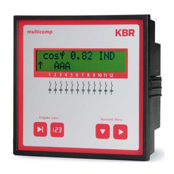
Operating instructions multicomp Operating and display panel multicomp 2F144-NC-1V1C6RO multicomp 2F144-NC-1V1C12RO Version 1.00 Page 3 of 29... - Page 10 Operating instructions multicomp Operating elements: LCD displaying current status and user prompts Number of controller output lines possible Two sensor buttons for parameter programming Two sensor buttons for menu selection General notes on operating the sensor buttons: Button Start input for configuration and reset. Button Value change during configuration Button...
-
Page 11: Mounting And Electrical Connection Of The Device
Operating instructions multicomp Mounting and electrical connection of the device General, very important! • Tighten all screws and connections as otherwise warranty will be void! • The device needs to be installed and operated in accordance with valid VDE regulations (in particular VDE 0100) and energy supplier regulations. -
Page 12: Standard Connection Chart Measurement Voltage Ph-N
Operating instructions multicomp Standard connection chart measurement voltage Ph-N only multicomp 2F144-NC-1V1C12RO For voltage supply, see nameplate. Page 6 of 29 Version 1.00... -
Page 13: Standard Connection Chart Measurement Voltage Ph-Ph
Operating instructions multicomp Standard connection chart measurement voltage Ph-Ph only multicomp 2F144-NC-1V1C12RO For voltage supply, see nameplate. Version 1.00 Page 7 of 29... -
Page 14: Commissioning The Facility
Operating instructions multicomp Commissioning the facility General commissioning notes • Switch on a sufficient number of inductive consumers (e.g. motors) prior to switching on the compensation facility. A transformer current of at least 15 mA needs to flow in the secondary circuit for the controller to be activated. -
Page 15: Navigation And Device Displays
Operating instructions multicomp Navigation and device displays Init Initialization period Start menu Stage state Service Commissioning Additional main menus next î D next î D next î D Inst. CosPhi Stage state Start menu Auto / off / on Service Commissioning Commissioning Measurement voltage... - Page 16 Operating instructions multicomp Start menu Switching Error message menu Extras performance next î D next î D next î D Switching Switching Error message menu Extras performance performance No meas. Display Attenuation I Hysteresis voltage language Connection Switching Switching Error message menu Extras performance performance...
-
Page 17: Main Menu Displays
Operating instructions multicomp Main menu displays For the current displays and the controller configuration, the following main menus with their submenus can be used: see item 5 Navigation and device displays: Note! In the next chapter, the main menus and their submenus are described in detail. - Page 18 Operating instructions multicomp Service window – display and deletion options S e r v i c e î D n e x t Commissioning window – entry of operating parameters C o m m i s s i o n i n g î...
-
Page 19: Description Of The Individual Display Windows
This menu is used for the initial commissioning of the controller, where all the necessary settings can be made. If a controller already integrated into a KBR compensation facility by default should be used, only the parameters of the current transformer have to be configured. - Page 20 Operating instructions multicomp Configuring current transformer values: For the compensation controller to function properly, all parameters concerning the current transformer have to be set correctly. Primary and secondary current of the transformer have to be set (submenu Iprim. / Isec.). These parameters can be read on the nameplate of the current transformer.
- Page 21 Operating instructions multicomp Function test: After all values have been programmed, a function test should be performed. To do so, the controller has to be taken off the voltage supply for a few seconds. After connecting it to the voltage supply, the controller has to start automatically. When reading out the CosPhi voltage in the start menu immediately after switching on, CosPhi should be inductive.
-
Page 22: Start Menu Window
Operating instructions multicomp Start menu window Exampel: 2F144-NC-1V1C12RO c o s ¢ 0 . 7 1 I N D A A A A This is displayed after the initialization window when the stage power has already been programmed. Here, the current total controller state and the currently measured CosPhi are measured. -
Page 23: Stage State Window
Operating instructions multicomp Stage state window S t a g e s t a t e î D n e x t Selection of submenus with button In the submenus of this window, it is displayed whether or not the capacitor stages connected are working in automatic operation, or if they are switched on or off permanently. -
Page 24: Commissioning Window
Operating instructions multicomp Commissioning window C o m m i s s i o n i n g î D n e x t Selection of submenus with button In the submenus of this window, a step-by-step description of the commissioning process is given. For facilities already in operation, the parameters set during commissioning can be read out here. - Page 25 Operating instructions multicomp Setting target CosPhi: You can ask your energy supply company for the target CosPhi, which should be set up at this point. The target CosPhi is by default set to 0.95 inductive (see chapter Default settings). Setting the voltage transformer parameters: Specify the primary voltage in the U primary submenu, the secondary voltage under U secondary and the phase allocation of the measurement voltage under Rot.field U.
-
Page 26: Switching Performance Window
Operating instructions multicomp Switching performance window S w i t c h . p e r f o r m . î D n e x t Selection of submenus with button In the submenus of this window, the settings made for the switching performance by default are displayed (default settings). -
Page 27: Error Message Menu
Operating instructions multicomp Error message menu M e s s a g e m e n u î D n e x t Selection of submenus with button In the submenus of this window, the possible messages are displayed, as well as the display configuration. The following error messages can be configured: Alarm submenu Possible actions... -
Page 28: Window Extras
Operating instructions multicomp Window Extras E x t r a s î D n e x t Selection of submenus with button In the submenus of this window, the additional settings possible are displayed. If a submenu is selected (using the button ), the settings can be changed by pressing the button to start entering values,... -
Page 29: Notes On Detecting Errors
Operating instructions multicomp Reset: With the item Reset, it is possible to reset the programmed parameters of the controller. Here, the programmable parameters are reset to default settings. A listing of the settings can be found in the appendix Technical Data. This has the advantage of all configured parameters to be deleted at once and the controller restarting with the default settings stored. -
Page 30: Facility And Safety Devices Maintenance
Operating instructions multicomp Facility and safety devices maintenance In order to ensure proper function and a long service life of your facility, the following checks have to be performed after commissioning and then once a year! • Check and retighten all connections. Screwed connections may become loose at the beginning due to thermal stress. -
Page 31: Setting Range Of The Parameters Configurable
Operating instructions multicomp 10 Setting range of the parameters configurable Primary voltage 1 V to 39999 V Ph-Ph Secondary voltage 1 V to 999 V Ph-Ph Primary current 1 A to 39999 A Secondary current 1 and 5 A Rot.field U L1N, L2N, L3N, L12, L23, L31 Rot.field I L1, L2, L3, -L1, -L2, -L3... -
Page 32: Technical Data
Operating instructions multicomp Technical Data 11.1 Measuring and display values Voltage Actual value of a measuring interval Phase - 0 or phase - phase, depending on programming Units [V, kV;] display is switched automatically Display range 0.00 kV to 99.9 kV Measuring range 30 ... -
Page 33: Device Memory
Operating instructions multicomp 11.4 Device memory Data storage 16 kB RAM volatile Program and parameter memory 128 kB flash Extreme values (Max.) Missing compensation power Q 11.5 Other limits Limit violations: acquisition time approx. 100 ms harmonics Overvoltage disconnect: acquisition time approx. -
Page 34: Mechanical Data
Operating instructions multicomp 11.9 Mechanical data Flush-mounted Housing measures 144 x 144 x 60 mm (H x W x D), device Mounting cutout 138 x 138 mm Mode of protection Front IP51 (with optionally available front door max. IP54), terminals IP20 Weight approx. -
Page 35: Selection Of Lines And Fuses
Operating instructions multicomp 12 Selection of lines and fuses C power Current input Supply line Fuse protection (400 V) per phase Cu (mm²) slow-blowing Q (kvar) I (A) 3 x I (A) 0.72 1.44 2.16 2.88 3.60 4.32 5.76 7.20 8.64 10.80 14.40... - Page 36 ERKLÄRUNG DER KONFORMITÄT DECLARATION OF CONFORMITY DÉCLARATION DE CONFORMITÉ KBR GmbH Schwabach We/Nous (Name des Anbieters / supplier´s name / norm du fournisseur) Am Kiefernschlag 7 D-91126 Schwabach (Anschrift / address / addresse) erklären in alleiniger Verantwortung, dass das (die) Produkt(e) / declare under our sole responsibility that the product(s) / Déclarons sous notre seule responsabilité, ques le(s) produit(s)
- Page 37 KBR GmbH KBR GmbH Abteilung Entwicklung Development Am Kiefernschlag 7 Am Kiefernschlag 7 D-91126 Schwabach D-91126 Schwabach / Germany Vorschläge: Suggestions: Korrekturen: Corrections: Betrifft Gerät: Device concerned Sollten Sie beim Lesen dieser Bedienungsanleitung oder If you come across misprints in this user manual or prin- Druckschrift auf Druckfehler gestoßen sein, bitten wir...
Need help?
Do you have a question about the Multicomp 2F144-NC-1V1C06RO and is the answer not in the manual?
Questions and answers