Table of Contents
Advertisement
Quick Links
Advertisement
Table of Contents

Related Manuals for Magnum Ranger


Summary of Contents for Magnum Ranger
- Page 1 Ranger PLEASE READ ME FIRST www.magnumbikes.com...
-
Page 2: Table Of Contents
CONTENTS 1. GENERAL INTRODUCTION 1.1 Welcome ................................... 01 1.2 Use of the Manual ..............................01 1.3 Service and Technical Support ..........................01 1.4 Bike Components ..............................01 1.4.1 Handlebar ................................01 1.4.2 E-bike ..................................02 1.5 Technical Data ................................02 2. -
Page 3: General Introduction
1. General Introduction 1.1 Welcome Thank you for purchasing a Magnum electric bike and welcome to the Magnum Bikes family of e-bike enthusiasts. We encourage you to join our Facebook group “Magnum Bikes Community” which you can find at the following link: https://www.facebook.com/groups/389290978573773... -
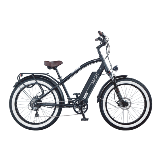
Page 4: E-Bike
13. Controller 20. Front Fork 7. Carrier 14. Battery 21. Tire 1.5 Technical Data Component Ranger 26" 48V Motor Das-Kit, X15-fat rear drive motor, 48V 750W(Max power) Battery I5-4813, 48V 13Ah, 768Wh, with USB port Display Das-Kit, C7, LCD, 6 levels... -
Page 5: Installation And Adjustment
INSTALLATION AND ADJUSTMENT 2. INSTALLATION AND ADJUSTMENT 2.1 Handlebar and Stem Assembly 1. Open the top cover, align the stem with the head tube 2. Align the handlebar to be perpendicular to the wheel, and slide it on. Tighten the screw at the top of the stem. then insert and tighten the two side-facing screws as shown below. -
Page 6: Assembly Of The Pedals
INSTALLATION AND ADJUSTMENT 2.2 Assembly of the Pedals - Identify your pedals: check the letters on the pedals, "L" or "R". - The "R" marked pedal is for the right (when facing the forward direction). For attachment to the crank, tighten clockwise. - The "L"... -
Page 7: Seat Position
INSTALLATION AND ADJUSTMENT 2.3 Seat Position To enable comfortable, fatigue-free and safe riding, the saddle and handlebar height should be adjusted to the body size of the rider. The saddle height is correct if the leg is near full extension while the foot is resting flat on the pedal in the bottom position of the crank cycle. -
Page 8: Saddle Height
INSTALLATION AND ADJUSTMENT 2.4 Saddle Height The quick-release lever must require noticeable effort to put into fully closed position to prevent any undesired movement while riding. WARNING: An improperly closed quick release lever can open again or have limited ability to keep the saddle in place. This may cause the saddle to suddenly drop into the seat tube, potentially leading to serious falls and injury. -
Page 9: Battery & Charger
BATTERY & CHARGER 3. Battery & Charger 3.1 Overview A Battery B Charging Socket C Battery Handlebar D Capacity Level Light E Power Button F USB Port (output: 5V 700mA) WARNING: (Sticker on the battery) Please ensure that the battery is locked in place before use. A AC Plug (type will vary) B Charger C Charging Indicator... -
Page 10: Display
DISPLAY 4. Display Instruction Manual 4.1 APPEARANCE A Better Display. A Smart Display. Easy View 4" Display Panel. Superior Anodizing Aluminum Alloy Frame. PMMA Waterproof Cable Housing. Easy Control with Large Buttons. - Page 11 DISPLAY 4.2 NORMAL OPERATION 4.1 PAS LEVEL SELECTION 4.2 ERROR CODE INDICATOR section 4 4.3 WALK MODE 4.4 SET OPERATION 3.1 BACKLIGHT section 3 3.2 SPEED INDICATOR 3.3 KM/H AND MPH section 2 CURRENT INDICATOR ON/OFF section 1 DOWN 5.1 DISTANCE INDICATOR 5.1.1 ODO 5.1.2 TIME section 5...
- Page 12 DISPLAY FULL VIEW AREA NORMAL VIEW AREA With the display on, the default indicators are riding mode, trip 2, speed, PAS level, and battery indicator as shown in the figure below. Press SET to change the display information.
- Page 13 DISPLAY Section 1: ON/OFF Press ON/OFF to activate the display. With the display on, press ON/OFF for 2 seconds to turn off power. With the display off, there is no battery power consumption. The panel will power off automatically when speed is 0 mph for 5 minutes. Section 2: CURRENT INDICATOR The current indicator shows the present discharging current of the controller: each segment is 2A, six segments are ≥...
- Page 14 DISPLAY 3.2 SPEED INDICATOR The central area displays the current riding speed of the E-bike. The speed display is as below. 3.3 KM/H and MPH Selecting KM/H or MPH for the speed and mileage will switch all indicators to the selected unit of measurement. Section 4: OPERATION 4.1 PAS LEVEL SELECTION Press UP (+) or DOWN (-) to change the PAS level and thus change the power output of the motor.
- Page 15 DISPLAY 4.2 ERROR CODE INDICATOR If there is something wrong with the electronic control system, the display will flash at 1Hz and show the error code automatically. Different error codes represent different faults in the system, consult the error code table on the last page for details(4.3).
- Page 16 DISPLAY 4.3 WALK MODE Hold DOWN (-) for 2 seconds to enter the power-assisted walk mode. When the 6KM icon is lit, the E-bike will travel at 3.7 mph without the need for the rider to pedal. Assisted walk mode will end when the DOWN (-) button is no longer being held.
- Page 17 DISPLAY Section 6: 6.1 BATTERY INDICATOR 6.1.1 Battery Residual Capacity Indicator The battery capacity indicator has five segments, each segment representing 20% of battery capacity. When the battery is full, the five segments are all lit. If the battery is low, the battery display area will flash, indicating that pedal assistance will soon cease and that the battery needs to be recharged.
- Page 18 Hall signal error (electromagnet in incorrect position) Brake error (detection after turning on) Under voltage Motor stalling Error in communication with controller Error in communication with display If you still some questions about the display, please contact your Magnum dealer.
-
Page 19: Recommendations And Maintenance
RECOMMENDATIONS AND MAINTENANCE 5. Recommendations and Maintenance 5.1 General Requirements E-bikes use metal shells to cover the electric components, so we strongly advise against the use of excessive water to wash the shells and parts around them. Use a soft cloth with a neutral solution to wipe the dirt off the shells. Afterward, wipe everything dry with a clean soft cloth. - Page 20 RECOMMENDATIONS AND MAINTENANCE Maintenance Schedule Each ride Weekly Monthly 6 Monthly Yearly Tire pressure Tire condition Visual inspection Brake lever pressure Quick releases Handlebar alignment Saddle alignment Battery pack locked Wheel check Inspect frame condition (include welds for fissures) Clean and lubricate chain Check brake pads Lubricate forks Lubricate brakes &...
-
Page 21: Definition Of Tampering And Recommendations
RECOMMENDATIONS AND MAINTENANCE 5.3 Definition of Tampering and Recommendations Category 1 Category 2 Category 3 Category 4 Components which can Components which can Components which can Components which can be only be replaced after only be replaced after only be replaced after replaced without approval approval from the bicycle approval from the bicycle... -
Page 22: Warranty
WARRANTY 6. Warranty Your MAGNUM E-bike comes with a limited warranty. Please visit www.magnumbikes.com or your local magnum dealer for details. Bike must be registered at www.magnumbikes.com/warranty in order to be covered by the one yeat warranty. Stay Connected @magnumbikes @magnumbikes www.magnumbikes.com... - Page 24 E-mail: info@magnumbikes.com | Phone: (323) 375-2666 | www.magnumbikes.com...
Need help?
Do you have a question about the Ranger and is the answer not in the manual?
Questions and answers