Table of Contents
Advertisement
Advertisement
Table of Contents

Related Manuals for Magnum Pathfinder T


Summary of Contents for Magnum Pathfinder T
- Page 1 Pathfinder T PLEASE READ ME FIRST www.magnumbikes.com...
-
Page 2: Table Of Contents
Contents 1. General Introduction 1.1 Welcome ..............................1.2 Use of Manual ............................1.3 Service and Technical Support ......................... 1.4 Bike Components ............................1.4.2 E-Bike ..............................1.5 Technical Data ............................2. Assembly and Adjustment 2.1 Handlebar and Stem Assembly ........................ 2.2 Assembly of the Pedals ..........................2.3 Seat Posistion ............................ -
Page 3: General Introduction
You should keep this manual along with any other documents that were included with your bicycle. All content in this manual is subject to change without notice. Magnum Bikes makes every effort to ensure accuracy of its documentation and assumes no responsibility of liability if any errors or inaccuracies appear within. -
Page 4: E-Bike
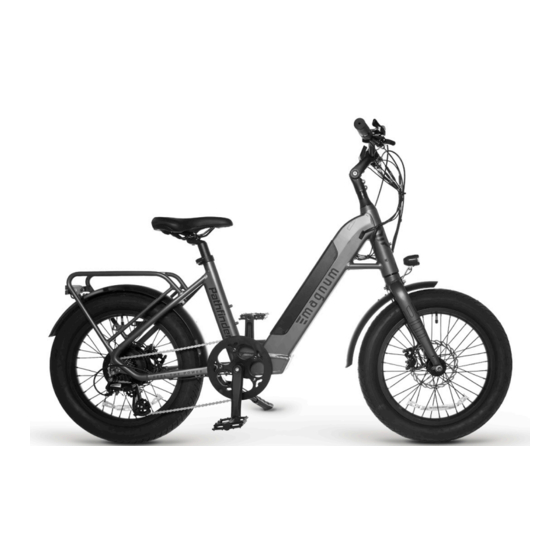
General 1.General Introduction 1.4 E-Bike 1. Rear Light 8. Controller 15. Pedal 22. Front Fender 2. Rear Fender 9. Water Bottle Mount 16. Kickstand 23. Valve Stem 3. Motor 10. Saddle Quick Release 17. Crankset 24. Front Fork 4. Freewheel 11. -
Page 5: Technical Data
General 1.General Introduction 1.5 Technical Data Component Motor 48V, 500W Rear Geared Hub Motor Battery 48V, 17.5Ah, 840Wh Li-ncm Display Bigstone H102 Display Throttle Twist Throttle Front Fork Rigid Fork Brake Levers Left and Right Brakes Hydraulic Disc Brakes Derailleur Shimano, Altus, 7-speed Freewheel 7-speed... -
Page 6: Handlebar And Stem Assembly
Installation & Adjustment 2.Installation and Adjustment 2.1 Handlebar and Stem Assembly 1. Loosen the screws on the faceplate of the stem. 2. Center the handlebar and put the faceplate back Remove the faceplate and set aside. in place. Tighten the 4 faceplate screws in a star pattern. -
Page 7: Assembly Of The Pedals
Installation & Adjustment 2.Installation and Adjustment 2.2 Assembly of the Pedals Identify your pedals: check the letters on the pedals, “L” or “R”. Right and left are the same as when you are riding the bike. The “R” and “L” marked pedals are for the right and lefts sides of the bike as if you were riding it. -
Page 8: Seat Posistion
Installation & Adjustment 2.Installation and Adjustment 2.3 Seat Position To enable comfortable, fatigue-free and safe riding, the saddle and handlebar height should be adjusted to the body size of the rider. The saddle height is correct if the leg is near full extension while the foot is resting flat on the pedal in the bottom position of the crank cycle. -
Page 9: Saddle Height
Installation & Adjustment 2.Installation and Adjustment 2.4 Saddle Height The quick-release lever must require noticeable effort to put into fully closed position to prevent any unde- sired movement while riding. WARNING An improperly closed quick release lever can open again or have limited ability to keep the saddle in place. This may cause the saddle to suddenly drop into the seat tube, potentially leading to serious falls and injury. -
Page 10: Battery And Charger
Battery & Charger 3.Battery and Charger 3.1 Overview Battery Power Button Power Indicator Charging Port WARNING Please ensure that the battery is locked in place before use AC Plug¹ Charger Charging Indicator Battery Plug 3.2 General Remarks Stop charging the battery immediately if you notice anything unusual, such as smoke or a strange smell; take out the battery and store it outside of the house, then take the battery to an authorized dealer or experi- enced technician for service or replacement. -
Page 11: Charging
Charging is completed when the charger’s LED turns green. Do not leave your battery charging overnight. Please use the original charger or a certified replacement charger from Magnum Bikes. The charger lights up in red during charging, and turns green when fully charged. Unplug the charger once the battery is full. -
Page 12: Display
Display 4. Display Appearance Powering ON/OFF Press and hold the power button (located above the top of the display screen) to turn on the display. - Page 13 Display 4. Display Indicators & Buttons Battery Level Speed Speed Units (Km or MPH) Lights Indicator Walk Mode Assist Level ODO, Trip, & Range Display Indicators Speed of rider Speed units chosen in the display settings Displays when walk mode is in use Displays when the lights are turned on Displays the active level of pedal assist Shows battery power left...
- Page 14 Display 4.Display Power On/Off Turn the battery ON, then press and hold the power button to turn the display ON. Press and hold the power button to turn the display OFF. Pedal Assist Level Press the increase arrow button to increase the level of pedal assist. Press the decrease arrow button to decrease the level of pedal assist.
- Page 15 Display 4.Display Display Settings Enter/Exit The Display Settings Menu Press the power button and increase arrow button at the time to enter the display settings menu. Press the power button and decrease arrow button at the same time to exit the display settings menu. Display Settings Menu Navigation Use the increase and decrease arrow buttons to move through the display settings menu.
- Page 16 Select km/h or mph and press the power button to set your option. Top Speed Setting Top speed is pre-set and can only be adjusted by entering the password. Consult a certified Magnum Bikes dealer or Magnum Bikes customer support if you need further assistance with your speed settings.
- Page 17 If you have a cadence sensor this setting should be set to “speed”. If you have a torque sensor this setting should be set to “torque”. Magnum “Pathfinder” will come with a cadence sensor. The Magnum “Pathfinder T” will come with a torque sensor. The T stands for torque.
-
Page 18: Recommendations And Maintenance
Recommendations & Maintenance 5. Recommendations and Maintenance 5.1 General Requirements E-bikes use metal shells to cover the electric components, we strongly advise against the use of excessive water to wash the shells and parts around them. Use a soft cloth with a neutral solution to wipe the dirt off the shells. - Page 19 Recommendations & Maintenance Maintenance Schedule Each Ride Weekly Monthly 6 Months Yearly Tire Pressure Tire Condition Visual Inspection Brake Lever Pressure Quick Releases Handlebar Alignment Saddle Alignment Battery Pack Locked Wheel Check Inspect Frame Condition¹ Clean & Lubricate Chain Check Brake Pads Lubricate Forks Lubricate Brakes &...
-
Page 20: Definition Of Tampering And Recommendations
Recommendations & Maintenance 5.3 Definition of Tampering and Recommendations Category 1 Components which can only be replaced after approval from the bicycle manufacturer/ electronic system provider Motor Controller Electric Cables Battery Sensors Display Controls Display Battery Charger Category 2 Components which can only be replaced after approval from the bicycle manufacturer Frame Hub-motor Wheel Brake Pads... -
Page 21: Warranty
Warranty 6. Warranty Your Magnum E-bike comes with a limited warranty. Please visit www.magnumbikes.com or your local Mag- num dealer for details. Bike must be registered at www.magnumbikes.com/warranty in order to be covered by the one year warranty. Stay Connected... - Page 22 E L E C T R I C B I K E S...
Need help?
Do you have a question about the Pathfinder T and is the answer not in the manual?
Questions and answers
Battery won’t charge
Need an on off switch for a Magnum Pathfinder E-bike 500