Advertisement
Quick Links
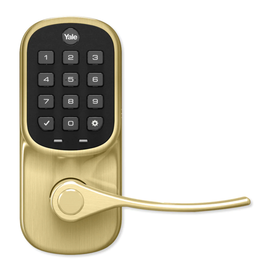
Yale Assure Lock Lever Push Button
®
®
Installation and Programming Instructions
®
(YRL216)
x2
#8-32 x 5/16"
Machine screws
x4
x2
#7 wood & #8-32
machine x 20mm
M4 x 22mm
Combination screws
Pan head machine
screws
AA Alkaline
Template
Batteries
Battery Cover
Key
Levers
Latch
Before you begin
Cylinder
DOWNLOAD
THE BILT APP
Optional
for step-by-step installation
Network Module
instructions & to register
Strike Plate
Battery Cover
your product
WARNING
This product can expose you to lead which is known to the state of
Keys
Interior Mounting Plate
California to cause cancer and birth defects or other reproductive harm.
Interior Lock
For more information go to www.P65warnings.ca.gov.
1
FAILURE TO FOLLOW THESE INSTRUCTIONS COULD RESULT IN DAMAGE TO THE PRODUCT AND VOID THE FACTORY WARRANTY
P/N YRL-LPBINSTL-FUL Rev D
Advertisement

Related Manuals for Yale Assure Lock Lever Push Button YRL216


Summary of Contents for Yale Assure Lock Lever Push Button YRL216
- Page 1 Yale Assure Lock Lever Push Button ® ® Installation and Programming Instructions ® (YRL216) #8-32 x 5/16" Machine screws #7 wood & #8-32 machine x 20mm M4 x 22mm Combination screws Pan head machine screws AA Alkaline Template Batteries Battery Cover...
-
Page 2: Preparing To Install
Preparing to Install Tools Needed Standard Phillips Head Screwdriver Tools necessary only for new doors or adjusting existing prep. Template Tape Pencil Measure Drill Wood Mortise Chisel Utility Knife Level 2-3/8" through bolt posts default *Backset PULL 2-3/4" through bolt posts Note: Adjustment based on backset *2-3/8"... -
Page 3: Checking Measurements
Checking Measurements 2-3/8" or 2-3/4" (60mm or 70mm) Backset 2-1/8" (54mm) Diameter 1-3/8" or 1-3/4" (35mm or 44.5mm) Door Thickness Door Prep Template P/N YRL-LPBINSTL-FUL Rev D... - Page 4 Determining Door Handing Inswinging Door Outswinging Door Interior Left Hand Right Hand Interior Reverse Reverse Left Hand Right Hand Exterior Exterior Face a door swinging open Face a door swinging open away from you. toward you. If it swings open to the right, If it swings open to the right, it it is a right hand door.
- Page 5 Preparing Door & Frame Necessary for new doors or adjusting existing prep. 2-1/8" Door Prep (54mm) Template Dia. 2-3/8" (60mm) 1" (25mm) 2-3/4" (70mm) Dia. Backset Drill holes 1/2 way through door then complete from other side to prevent splitting. Frame Frame Inside...
- Page 6 Installing Latch & Strike Plate Right Hand Installation Shown Outside of Door Frame P/N YRL-LPBINSTL-FUL Rev D...
- Page 7 Installing Push Button Right Hand Installation Shown “TOP” mark must be on top surface and tailpiece in vertical position. Incorrect orientation will cause lock to fail. Outside of Right Hand Door Inside of Right Hand Door P/N YRL-LPBINSTL-FUL Rev D...
- Page 8 Installing Interior Mounting Plate Right Hand Installation Shown Inside of Right Hand Door Inside of Right Hand Door P/N YRL-LPBINSTL-FUL Rev D...
- Page 9 Attaching the Cable Assembly Right Hand Installation Shown Inside of Right Hand Door P/N YRL-LPBINSTL-FUL Rev D...
- Page 10 Installing Interior Lock Right Hand Installation Shown Inside of Right Hand Door “Click” P/N YRL-LPBINSTL-FUL Rev D...
- Page 11 Installing Exterior Cylinder Outside of Right Hand Door Latch Cylinder must be installed with bar away from latch. P/N YRL-LPBINSTL-FUL Rev D...
- Page 12 Installing Exterior Lever Outside of Right Hand Door Press pin while installing lever so lock is not damaged. Installing Interior Lever Inside of Right Hand Door Press pin while installing lever so lock is not damaged. P/N YRL-LPBINSTL-FUL Rev D...
- Page 13 Testing Thumbturn Operation Test with door open. Outside of Right Hand Door Outside of Right Hand Door If thumbturn operation test fails, check installation beginning with Step 3. P/N YRL-LPBINSTL-FUL Rev D...
- Page 14 Testing Key Operation Test with door open. Outside of Right Hand Door Outside of Right Hand Door If key operation test fails, check installation beginning with Step 6. P/N YRL-LPBINSTL-FUL Rev D...
- Page 15 Installing Optional Network Module Inside of Right Hand Door NOTE: If a network module was included with your lock, it is in a separate box with additional module installation instructions. P/N YRL-LPBINSTL-FUL Rev D...
- Page 16 Installing Batteries & Cover Inside of Right Hand Door Congratulations, you've installed the ® ® Yale Assure Lock Lever Push Button ( YRL216 Using Your Lock instructions will help you customize your lock. P/N YRL-LPBINSTL-FUL Rev D...
- Page 17 Testing Push Button Operation Test with door open. A Master PIN Code must be created upon installation or after resetting the lock to factory default. Programming and use of lock is not possible until this step has been successfully completed. See of Programming Instructions below.
- Page 18 Resetting Lock to Factory Default Interior Lock Reset Button When resetting the lock, all user codes, including the Master PIN code*, are deleted. All programming features are reset to original default settings. See “Factory Settings”. 1. Remove the battery cover and batteries. 2.
-
Page 19: Hardware Troubleshooting
Hardware Troubleshooting Cycle lock in both the locked and unlocked positions. If problems are found: Tailpiece and spindle will not mate and fit into the interior escutcheon a. Ensure that your door is between 1-3/8" and 1-3/4" thick b. Ensure that the square shaped spindle has “Top” writing and arrow facing upwards c. -
Page 20: Setting Definitions
Setting Definitions Settings Default Setting Definition The Master Entry Code is used for programming and for feature settings. It must be created prior to Creation Master Entry Code required* programming the lock. The Master code will also operate (unlock/lock) the lock. This feature is enabled by the Master Entry Code. - Page 21 Using Your Lock Push Button Keypad Low Battery Indicator (flashes red) Press any key All Code Lockout Mode to wake keypad (keypad flashes) Speaker Press to enter or unlock Enter Master Entry Code and press to access Settings Menu Battery Back-up Hold a 9V battery to the terminals in case of dead lock batteries and no key...
- Page 22 Creating Master Entry Code Creating a Master Entry Code must be performed upon installation or after resetting the lock to factory default. Programming and use of lock is not possible until this step has been successfully completed. Press Press Press Enter 4-8 digit Master Entry Code...
- Page 23 Creating User Entry Codes Master Entry code must be created first. *Max user codes = 250 with Network Module. Max user codes = 25 without. Enter Master Entry code Press Press Enter 4-8 digit Entry code Press Press Press Press (code flashes) Adding more User Codes: To end programming:...
- Page 24 Deleting Entry Codes Enter Master Entry Code Press Press Press Press Press Deleting one entry code: To delete all entry codes (Does not delete To delete one entry code, Master Entry Code): you must enter the entry code you wish to delete. Enter 4-8 digit entry code Enter Press...
- Page 25 Unlocking Door with Entry Code Enter Entry Code Press Code Chart Duplicate if necessary Entry Code Management Entry Code Master: User Name: P/N YRL-LPBINSTL-FUL Rev D...
- Page 26 Here is an example of how to set Auto Lock to 30 seconds: Master Entry Code *The Master Entry Code must be created prior to any other programming of the lock. **Network Module Setting function appears only with Yale Smart module installed. P/N YRL-LPBINSTL-FUL Rev D...
-
Page 27: Programming Troubleshooting
Code can enable/disable All Code Lockout Mode. Contact the Master user. The Yale logo displays intermittent RED flashes. * When batteries are replaced, Smart Module locks have a real time clock that will be set through the User Interface (UI); it is recommended to verify correct date and time particularly those locks operating under Daylight Saving Time (DST). - Page 28 Cet appareillage numérique de la classe A répond à toutes les exigences de l'interférence canadienne causant des règlements d'équipement. Product Support Tel 1-855-213-5841 • www.yalehome.com Yale®, Yale Real Living® and Assure Lock® are registered trademarks of ASSA ABLOY Residential Group. Other products’ brand names may be trademarks or registered trademarks of their respective owners and are mentioned for reference purposes only.
- Page 29 • Remove battery cover • Remove batteries • Insert or remove Yale Smart Module • Reinstall batteries • Reinstall battery cover 6. If you're adding a new Yale Smart Module, follow the instructions included with it P/N AYR202-ZW-INSTAL-FUL Rev E...
- Page 30 CAN ICES-3B/NMB-3B 24/7 Tech Support : 1-855-492-0505 • www.yalehome.com Yale® is a registered trademark of ASSA ABLOY Residential Group. Other products' brand names may be trademarks or registered trademarks of their respective owners and are mentioned for reference purposes only. © Copyright 2019. All rights reserved. Reproduction in whole or in part without the...
- Page 31 Yale ZigBee Module ® ® ® Installation and Programming Instructions Installing the ZigBee Module ® IMPORTANT: the batteries must be removed prior to removing and/or inserting the network module: • Remove battery cover. • Remove batteries. • Remove and/or insert network module.
- Page 32 Copyright © 2017, Yale Security Inc., an ASSA ABLOY Group company. All rights reserved. Reproduction in whole or in part without the express written permission of Yale Security Inc. is prohibited. YALE, with its unique global reach and range of products, is the world's favorite lock –...
Need help?
Do you have a question about the Assure Lock Lever Push Button YRL216 and is the answer not in the manual?
Questions and answers