Advertisement
SELECTRONIC
Moments
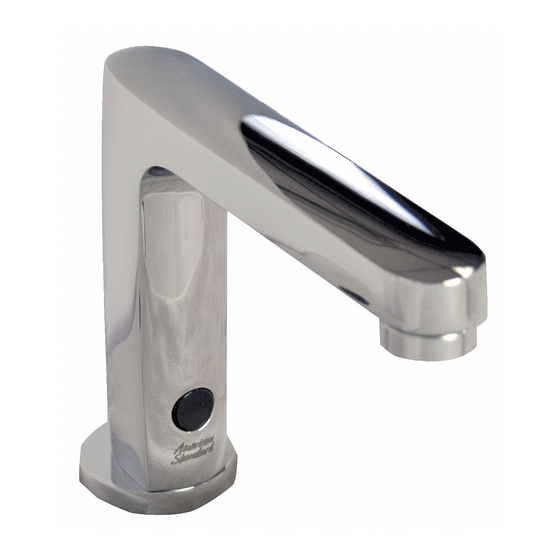
Proximity Faucets
© 2007 American Standard
M965653 (11/14)
Certified to comply with ASME A112.18.1
© 2014 American Standard
NOTE TO INSTALLER: Please give this manual to the customer after installation.
NOTE TO INSTALLER: Please give this manual to the customer after installation.
To learn more about American Standard Selectronic
or e-mail us at: CRTTEAM@americanstandard.com
For Parts, Service, Warranty or other Assistance,
please call (844) CRT-TEAM / (844) 278-8326
®
CAUTION: Use only American Standard
supplied cable sets. Using non-AS supplied
cables, or cutting, splicing or modifying any
components will void the warranty.
Product No.'s & Options
Specifications
Faucet Installation
Electrical Installation
Start-up / Maintenance
FAQ's / Troubleshooting
Parts
Products visit our website at: www.americanstandard-us.com
®
(In Canada: 1-800-387-0369)
(In Toronto Area only: 1-905-306-1093)
MODEL NUMBERS
2506.1X2 2506.1X3 2506.1X5
1
2
2-3
4-6
7-8
8-9
10
Advertisement
Table of Contents

Subscribe to Our Youtube Channel
Related Manuals for American Standard SELECTRONIC 2506.1X2


Summary of Contents for American Standard SELECTRONIC 2506.1X2
- Page 1 © 2014 American Standard NOTE TO INSTALLER: Please give this manual to the customer after installation. NOTE TO INSTALLER: Please give this manual to the customer after installation. To learn more about American Standard Selectronic Products visit our website at: www.americanstandard-us.com ®...
- Page 2 UNPACKING All American Standard Faucets Are Water Tested At Our Factory. Some Residual Water May Remain In The Faucet During Shipping. The illustration below shows the fitting and all loose items after they have been removed from the carton.
-
Page 3: Installation
49mm 32mm (1-1/4) installed in accordance with applicable codes, regulations and standards. 125mm (4-7/8) CAUTION: Use only American Standard supplied cable sets. Using non-AS supplied 114mm (4-1/2) cables, or cutting, splicing or modifying any SEE DETAIL “A” components will void the warranty. - Page 4 MOUNT ENCLOSURE; Fig. 2 Fig. 2 LAVATORY RIM OR etermine location of ENCLOSURE (1). It must be 1. D MOUNTING SURFACE located with-in the 14" (356mm) by 21" (533mm) shaded area shown in Figure 2 in order for electrical 14" connections from the spout assembly to be made.
-
Page 5: Electrical Installation
Fig. 1d. 6. Replace ENCLOSURE COVER (1). Tighten cover screws firmly. STANDARD BATTERY CAUTION: Use only American Standard supplied LONG LIFE POWER PACK cable sets. Using non-AS supplied cables, or cutting, splicing or modifying any components will void the warranty. - Page 6 8b. Connect the10' EXTENSION (10b) to the POWER SUPPLY 4" ELECTRICAL BOX OR EQUIVALENT BY CABLE (15). Fig. 2c. OTHERS CAUTION: Use only American Standard supplied cable sets. Using non-AS supplied cables, or cutting, splicing or modifying any BLACK & WHITE components will void the warranty.
- Page 7 6. Repeat Steps above for each additional Unit, for a Max. of 15 Units on one AC POWER SUPPLY. 7. Replace ENCLOSURE COVERS. Tighten cover screws firmly. CAUTION: Use only American Standard supplied cable sets. Using non-AS supplied cables, or cutting, splicing or modifying any components will void the warranty.
-
Page 8: Maintenance
MAINTENANCE Fig. 1 HAND WASH SENSOR OPERATION; Fig. 1 When the Sensor detects a user, the water immediately starts to flow. Water flow will stop 2 seconds after user is out of sensor range. The off delay allows the user to comfortably move his hands without the flow cycling on and off. - Page 9 INSTALL / REPLACE THE BATTERY or Fig. 4 LONG LIFE POWER PACK; Fig. 4 1. Remove COVER from ENCLOSURE (1). STANDARD BATTERY 2. Disconnect BATTERY HOLDER (3) from 27" EXTENSION CABLE (5). 3. Remove old BATTERY from BATTERY HOLDER (3). Install new BATTERY (2) making sure the terminal side is inserted first and shape of the battery follows the shape of the BATTERY HOLDER (3).
-
Page 10: Troubleshooting Flowcharts
Produ ct na m es l i s ted herei n are tradem ar ks of AS A m er i ca, In c . ©2 014 To learn more about American Standard Selectronic® Products visit our website at: www.americanstandard-us.com or e-mail us at: CRTTEAM@americanstandard.com...
Need help?
Do you have a question about the SELECTRONIC 2506.1X2 and is the answer not in the manual?
Questions and answers