Table of Contents

Subscribe to Our Youtube Channel
Related Manuals for Resol DeltaSol C/1


Summary of Contents for Resol DeltaSol C/1
- Page 1 ® RESOL D e lt a S o l Mounting Connection Operation Troubleshooting Examples Manuel Thank you for buying this RESOL product. Please read this manual carefully, to get the best performance from this unit. www.resol.com...
-
Page 2: Table Of Contents
CE-Declaration of conformity nance work. The product complies with the relevant directives and is - Initial installation should be carried therefore labelled with the CE mark. The Declaration of out by named qualified personnel Conformity is available upon request, please contact RESOL. -
Page 3: Overview Of Functions And Technical Data
• heat quantity balancing • function control • user-friendly operation through easy handling • easy-to-mount housing in outstanding design • RESOL VBus ® Scope of delivery: 1 x D e lt a S o l ® 1 x accessory bag... -
Page 4: Installation
® Example D e lt a S o l ® standard solar system Order notes RESOL D e lt a S o l ® RESOL D e lt a S o l C/1 - Full kit ® incl. 2 temperature sensors Pt1000 (1 x FKP6, 1 x FRP6) -
Page 5: Electrical Connection
19 = neutral conductor N 20 = conductor L 12 = ground clamp The controller is equipped with the RESOL VBus ® data transfer with and energy supply to external modules. The connection is carried out at the two terminals 9 and 10 marked “VBus... -
Page 6: Operation And Function
D e lt a S o l ® Operation and function Connect the controller to the mains. The controller is in an initialisation phase. After this phase, the controller is in Commissioning and buttons for automatic operation with factory settings. adjustment The controller is then ready for operation and normally the factory settings will give close to optimum operation. -
Page 7: System-Screen
D e lt a S o l ® 2.2.3 System-Screen The system screen (active arrangement) shows the scheme which has been selected. The screen consists of several system component symbols, which are - depending on the current status of the system - either flashing, permanently shown or „hidden“. -
Page 8: Control Parameters And Dislpay Channels
D e lt a S o l ® Control parameters and display channels 3.1 Overview of channels Legend: Only if the option heat quantity measurement is activated Corresponding channel is available. (OHQM), will the corresponding channel be available. Corresponding channel is available when the corresponding Only if the option heat quantity measurement is deactivated option is enabled... -
Page 9: Display Channels
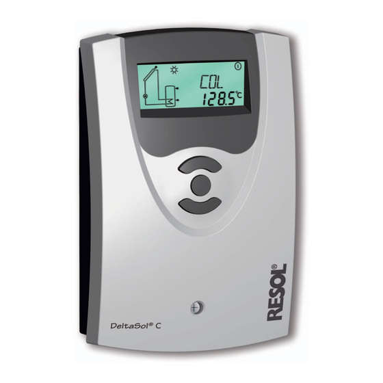
D e lt a S o l ® 3.1.1 Collector temperature Displays the actual collector temperature. COL: Collector temperature • COL : collector temperature Display range: -40 ... +250 °C 3.1.2 Store temperatures TST: Displays the actual store temperature. Store temperature •... -
Page 10: Adjustment Channels
D e lt a S o l ® 3.1.6Heat quantity measurement OHQM: Heat quantity Heat quantity measurement is possible if a flowmeter is measurement used. For this purpose, the heat quantity measurement op- Adjustment range: OFF...ON- tion OHQM has to be enabled. Factory setting: OFF The flow rate should be read from the flowmeter (l/min) and has to be adjusted in the channel FMAX. - Page 11 D e lt a S o l ® 3.1.8 Store maximum temperature S MX: Maximum store tem- If the adjusted maximum temperature is exceeded, the store perature will no longer be loaded in order to avoid damage caused by Adjustment range: 2 ... 95 °C overheating.
- Page 12 D e lt a S o l ® 3.1.12 Antifreeze function The antifreeze function activates the loading circuit between the collector and the store when the temperature falls be- OCF: Antifreeze function low the adjusted antifreeze temperature. This will protect Adjustment range: OFF / ON the fluid against freezing or coagulating.
-
Page 13: Troubleshooting
D e lt a S o l ® 4. Troubleshooting If a malfunction occurs, a notification is given on the display of the controller: fuse T2A Warning symbol 100 ... 240 V~ IP 20 50-60 Hz VBus On the display appears the symbol and the symbol Sensor defect. -
Page 14: Various
D e lt a S o l ® 5.1Various: Pump is overheated, but no heat transfer from collector Pump starts for a short moment, switches-off, switches-on to the store, feed flow and return flow are equally warm, again, etc. („controller hunting“) perhaps also bubble in the lines. - Page 15 D e lt a S o l ® Stores are cooled during the night. Control the return flow Please also check further preventer in warm water pumps which are con- circulation- o.k. nected to the solar store. Does collector circuit pump run during the night? Check the controller...
-
Page 16: Accessory
Overvoltage protection We highly recommend to install the RESOL overvoltage protection in order to avoid overvoltage damages at the collector (e.g. by lightening). Distributed by: RESOL - Elektronische Regelungen GmbH Heiskampstraße 10...
Need help?
Do you have a question about the DeltaSol C/1 and is the answer not in the manual?
Questions and answers