
Subscribe to Our Youtube Channel
Related Manuals for Resol DeltaSol C2


Summary of Contents for Resol DeltaSol C2
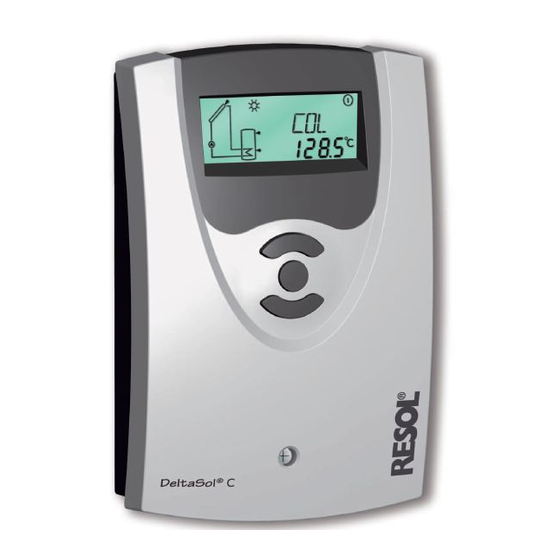
- Page 1 ® RESOL D e lt a S o l Mounting Connection Operation Troubleshooting Examples Manual Thank you for buying this RESOL product. Please read this manual carefully, to get the best performance from this unit. www.resol.de...
-
Page 2: Table Of Contents
CE mark. injury, can occur. The Declaration of Conformity is available upon ATTENTION means that damage to the appliance can request, please contact RESOL. occur. Note Note Notes are indicated with an information Strong electromagnetic fields can impair the symbol. -
Page 3: Overview Of Functions And Technical Data
• heat quantity measurement • function control • user-friendly operation through easy handling • easy-to-mount housing in outstanding design • RESOL VBus ® Scope of delivery: 1 x D e lt a S o l ® 1 x accessory bag... -
Page 4: Installation
® Example D e lt a S o l ® standard solar system Order notes RESOL D e lt a S o l ® RESOL D e lt a S o l C/2 - Full kit ® incl. 2 temperature sensors Pt1000 (1 x FKP6, 1 x FRP6) -
Page 5: Electrical Connection
Note: 12 = ground clamp The relay is a semiconductor relay for pump speed control. The controller is equipped with the RESOL VBus ® The minimum pump speed must be set to 100% when au- data transfer with and energy supply to external modules. -
Page 6: Operation And Function
D e lt a S o l ® Operation and function Connect the controller to the mains. The controller is in an initialisation phase. After this phase, the controller is in Commissioning and buttons for automatic operation with factory settings. adjustment The controller is then ready for operation and normally the factory settings will give close to optimum operation. -
Page 7: System-Screen
D e lt a S o l ® 2.2.3 System-Screen The system screen (active arrangement) shows the scheme which has been selected. The screen consists of several system component symbols, which are - depending on the current status of the system - either flashing, permanently shown or „hidden“. -
Page 8: Overview Of Channels
D e lt a S o l ® Control parameters and display channels 3.1 Overview of channels Legend: Only if the option heat quantity measurement is activated Corresponding channel is available. (OHQM), will the corresponding channel be available. Corresponding channel is available when the corresponding Only if the option heat quantity measurement is deactivated option is enabled... -
Page 9: Display Channels
D e lt a S o l ® 3.1.1 Collector temperature Displays the actual collector temperature. COL: Collector temperature • COL : collector temperature Display range: -40 ... +250 °C 3.1.2 Store temperatures TST: Displays the actual store temperature. Store temperature •... -
Page 10: Adjustment Channels
D e lt a S o l ® 3.1.7 Heat quantity measurement OHQM: Heat quantity Heat quantity measurement is possible if a flowmeter is measurement used. For this purpose, the heat quantity measurement op- Adjustment range: OFF...ON- tion OHQM has to be enabled. Factory setting: OFF The flow rate should be read from the flowmeter (l/min) and has to be adjusted in the channel FMAX. - Page 11 D e lt a S o l ® 3.1.8 ∆T -regulation DT O: This function is a standard differential control. If the switch- Switch-on temperature diff. on differential is reached (DT O), the pump is operated. The Adjustment range: 1,0...20,0 K pump runs at 100% speed for 10 seconds.
- Page 12 D e lt a S o l ® 3.1.11 System cooling When the adjusted maximum store temperature is reached, the system stagnates. If the collector temperature increases OCX Option system cooling to the adjusted maximum collector temperature (CMX) Adjustment range: OFF ... ON the solar pump is activated until the collector temperature Factory setting: OFF falls below the maximum collector temperature.
- Page 13 D e lt a S o l ® If the controller detects an increase in collector tempera- 3.1.15 Tube collector function ture by 2 K compared to the previously stored collector temperature, the solar pump will be switched-on for about O TC: 30 seconds in order to detect the fluid temperature.
-
Page 14: Troubleshooting
D e lt a S o l ® 4. Troubleshooting If a malfunction occurs, a notification is given on the display of the controller: fuse T2A Warning symbol 100 ... 240 V~ 50-60 Hz IP 20 1 (1) A (100 ... 240) V~ Temp. -
Page 15: Various
D e lt a S o l ® 4.1 Various: Pump is overheated, but no heat transfer from collector Pump starts for a short moment, switches-off, switches-on to the store, feed flow and return flow are equally warm, again, etc. („controller hunting“) perhaps also bubble in the lines. - Page 16 D e lt a S o l ® Stores are cooled during the night. Control the return flow Please also check further preventer in warm water pumps which are con- circulation- o.k. nected to the solar store. Does collector circuit pump run during the night? Check the controller...
-
Page 17: Accessory
With its standard mini-USB port it enables a fast transmission of system data via the VBus for processing, visualizing and ® archiving. A full version of the RESOL ServiceCenter soft- ware is included. - Page 18 D e lt a S o l ® Notes...
- Page 19 D e lt a S o l ® Notes...
-
Page 20: Imprint
As copyrighted. Another use outside the copyright requires the approval of RESOL - Elektronische Regelungen GmbH. faults can never be excluded, please note: Your own calcu- This especially applies for copies, translations, micro films lations and plans, under consideration of the current stan- and the storage into electronic systems.
Need help?
Do you have a question about the DeltaSol C2 and is the answer not in the manual?
Questions and answers