Table of Contents
Advertisement
DeltaSol
Solar controller for standard solar thermal systems
Manual for the
specialised craftsman
Installation
Operation
Functions and options
Troubleshooting
The cTUVus certification confirms that
the controller is certified to UL 60730-
1:2009 and CSA B60730.1:2002.
Thank you for buying this RESOL product.
Please read this manual carefully to get the best performance from this unit.
Please keep this manual safe.
AL
®
en
Manual
www.resol.com
Advertisement
Table of Contents

Related Manuals for Resol DeltaSol AL


Summary of Contents for Resol DeltaSol AL
- Page 1 The cTUVus certification confirms that the controller is certified to UL 60730- 1:2009 and CSA B60730.1:2002. Thank you for buying this RESOL product. Manual Please read this manual carefully to get the best performance from this unit. Please keep this manual safe.
- Page 2 Safety advice Target group Please pay attention to the following safety advice in order to avoid danger and These instructions are exclusively addressed to authorised skilled personnel. damage to people and property. Only qualified electricians should carry out electrical works. Initial installation must be effected by the system owner or qualified personnel Instructions named by the system owner.
-
Page 3: Table Of Contents
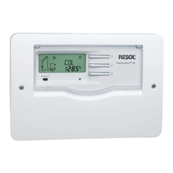
The DeltaSol AL is a temperature differential controller that offers all the vital ® For data communication, the controller is equipped with the RESOL VBus ® . Oper- functions for a standard solar thermal system. The controller is equipped with the ation and function control are straight forward. -
Page 4: Overview
• Intuitive operating concept Supply connection: type Y attachment • Unit °F and °C selectable Standby: 0.33 W Mode of operation: type 1.B action Rated impulse voltage: 2.5 kV Data interface: RESOL VBus Upper fastening ® VBus current supply: 35 mA ®... -
Page 5: Installation
Installation Mounting WARNING! Electric shock! Upon opening the housing, live parts are exposed! Î Always disconnect the device from power supply before opening the housing! 0 Auto I 0 Auto I 0 Auto I Note Strong electromagnetic fields can impair the function of the device. Î... -
Page 6: Electrical Connection
Sensor 2 (e. g. sensor store) of the installation! Sensor 3 (e. g. sensor store top) Note Connect the RESOL VBus to the terminals marked VBus with either polarity: ® It must be possible to disconnect the device from the mains at any time. -
Page 7: Data Communication / Bus
® supply to external modules. The connection is to be carried out at the two termi- sensors S1/S2 can also be used for heat quantity measurement. nals marked VBus (any polarity). One or more RESOL VBus modules can be ®... -
Page 8: Operation And Function
System-Monitoring-Display Operation and function Buttons The controller is operated via the 3 buttons next to the display: Button : Scrolling upwards, increasing adjustment values Button : Ⓢ Confirmation / selection The System-Monitoring-Display consists of 3 blocks: channel display, tool bar Button : Scrolling downwards, reducing adjustment values and system screen. -
Page 9: Slide Switch
3.2.3 System screen Slide switch The system scheme is indicated on the System-Monitoring-Display. It consists of By means of the slide switch the relay can be manually switched on (I), switched off several system component symbols which are – depending on the current status of (0) or put into automatic mode (Auto). -
Page 10: Control Parameters And Display Channels
Control parameters and display channels Channel overview Display channels Note Display of collector temperature Only if the temperature sensor is connected, will S3 be displayed! Display channels Channel Description Connection terminal Page x Temperature collector x Temperature store base Collector temperature x Temperature sensor 3 Display range: -40 …... -
Page 11: Adjustment Channels
Adjustment channels Operating hours counter Access to adjustment channels: Î Use button in order to scroll to the last display channel, then press and hold down button for approx. 3 s. ∆T control Operating hours counter Display channel The operating hours counter accumulates the operating hours (h P) of the relay. - Page 12 Maximum store temperature Collector cooling S MX Collector cooling option Collector maximum temperature Maximum store temperature Adjustment range: 4 … 95 °C [40 … 200 °F] Selection: OFF / ON Adjustment range: 100 … 190 °C Factory setting: OFF [210 … 380 °F] Factory setting: 60 °C [140 °F] Factory setting: 120 °C [250 °F] Hysteresis 2 K [4 °Ra]...
- Page 13 Minimum collector limitation Recooling function OREC Collector minimum limitation option Minimum collector temperature Recooling option Selection: OFF / ON Adjustment range: 10 … 90 °C Selection: OFF / ON Factory setting: OFF [50 … 200 °F] Factory setting: OFF Factory setting: 10 °C [50 °F] If the store temperature reaches the adjusted maximum store temperature If the collector minimum limitation option is activated, the pump (R1) is only (S MX), the controller keeps the solar pump running in order to prevent the col-...
- Page 14 Tube collector function Heat quantity measurement FMAX O TC Flow rate in l/min Tube collector function Adjustment range: 0 … 20 Adjustment range: OFF / ON in steps of 0.1 Factory setting: OFF Factory setting: 6.0 This function is used for improving the switch-on behaviour in systems with non-ideal sensor positions (e.
- Page 15 Temperature unit °C UNIT Temperature unit Selection: °C / °F Factory setting: °C In this adjustment channel, the display unit for temperatures and temperature dif- ferences can be chosen. The unit can be switched between °C / K and °F / °Ra during operation.
-
Page 16: Troubleshooting
1213 Fuse 1232 1000 1252 1019 1271 1039 1290 1058 1309 1078 1328 1097 1347 1117 1366 1136 1385 1155 1404 1175 1423 1194 1442 Resistance values of Pt1000 sensors Note For answers to frequently asked questions (FAQ) see www.resol.com. - Page 17 Pump starts up very late. Operating control LED is permanently off. Switch-on temperature difference If the operating control LED is off, check the power supply of the controller. Is ∆Ton too large? it disconnected? Change ∆Ton and ∆Toff corre- spondingly. The fuse of the controller could be Check the supply line and recon- Non-ideal position of the collector...
- Page 18 The solar circuit pump does not work, although the collector is considerably warmer than the store Insulation close enough to the store? Is the operating control LED on? Replace insulation or increase it. There is no current; check fuses / re- Are the store connections insulated? place them and check power supply.
-
Page 19: Accessories
RESOL VBus ® . It can be connected directly to a PC or router for remote displays are connected to the controller by means of the RESOL VBus ® remote access and thus enables comfortable system monitoring for yield monitor-... - Page 20 This mounting- and operation manual including all parts is copyrighted. Another some examples. They can only be used at your own risk. No liability is assumed for use outside the copyright requires the approval of RESOL – Elektronische Rege- incorrect, incomplete or false information and / or the resulting damages.
Need help?
Do you have a question about the DeltaSol AL and is the answer not in the manual?
Questions and answers