Table of Contents
Advertisement
Quick Links
®
CS/2
DeltaSol
Version 1.11
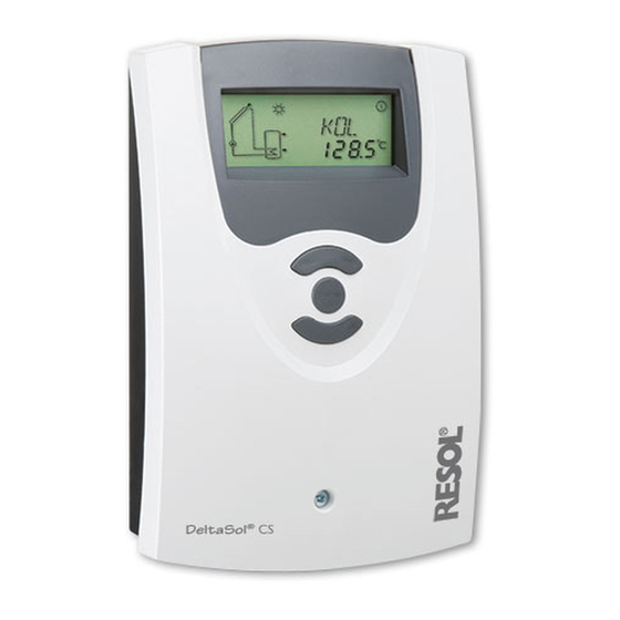
Solar controller
Manual for the
specialised craftsman
Installation
Operation
Functions and options
Troubleshooting
en
Thank you for buying this RESOL product.
Manual
Please read this manual carefully to get the best performance from this unit.
Please keep this manual carefully.
www.resol.com
Advertisement
Table of Contents

Related Manuals for Resol DeltaSol CS/2


Summary of Contents for Resol DeltaSol CS/2
-
Page 1: Medt X* Antifreeze Type
Solar controller Manual for the specialised craftsman Installation Operation Functions and options Troubleshooting Thank you for buying this RESOL product. Manual Please read this manual carefully to get the best performance from this unit. Please keep this manual carefully. www.resol.com... -
Page 2: Sen X* Vfd Allocation
Safety advice Target group Please pay attention to the following safety advice in order to avoid danger and These instructions are exclusively addressed to authorised skilled personnel. damage to people and property. Only qualified electricians are allowed to carry out electrical works Initial commissioning must be effected by the system installer or qualified personnel Instructions named by the system installer. -
Page 3: Table Of Contents
Solar controller DeltaSol CS/2 ® The DeltaSol CS/2 controller is used for the speed control of a HE pump in ® small standard solar thermal and heating systems. It is equipped with a PWM output and an additional input for a VFD Grundfos Di- rect Sensor that enables a precise heat quantity measurement. -
Page 4: Overview
Standby: 0.58 W • Unit °F and °C selectable Mode of operation: type 1.C.Y action Rated impulse voltage: 2.5 kV Upper fastening Data interface: RESOL VBus ® VBus current supply: 35 mA ® Functions: function control, operating hours counter, speed control, drainback... -
Page 5: Installation
Installation Mounting display WARNING! Electric shock! Upon opening the housing, live parts are exposed! Î Always disconnect the device from power supply before opening the housing! cover button Note Strong electromagnetic fields can impair the function of the controller. Î Make sure the controller as well as the system are not exposed to strong electromagnetic fields. -
Page 6: Vfd Grundfos Direct Sensor
VBus ® /USB or VBus ® /LAN interface adapter (not included). Different 100 ... 240 V~ solutions for visualisation and remote parameterisation are availabe on the RESOL 50-60 Hz IP 20 website www.resol.com. Note 1 (1) A 240 V~ Temp. -
Page 7: Terminal Allocation
Terminal allocation Sensors S3 and S4 can optionally be connected. S3 can optionally be used as the The controller calculates the temperature difference between collector sensor S1 reference sensor for the store emergency shutdown option (OSEM). and store sensor S2. If the difference is larger than or identical to the adjusted switch-on temperature difference (DT O), the solar pump will be activated by relay If heat quantity measurement (OHQM) is activated, S4 and VFD are used as the 1, and the store will be loaded until the switch-off temperature difference (DT F) or... - Page 8 Display channels Adjustment channels Channel Description Connection terminal Page Channel Description Factory setting Page INIT x* ODB initialisation active DTCO x* Switch-on temperature difference cooling 20.0 K [40.0 °Ra] x* ODB filling time active DTCF x* Switch-off temperature difference cooling 15.0 K [30.0 °Ra] STAB x* ODB stabilisation in progress...
-
Page 9: Operation And Function
Operation and function System-Monitoring-Display Buttons System-Monitoring-Display forwards (+) Ⓢ (selection / The System-Monitoring-Display consists of 3 blocks: channel display, tool bar and adjustment mode) system screen. backwards (-) Channel display The controller is operated via the 3 push buttons below the display. Button 1 (+) is used for scrolling forwards through the menu and increasing adjustment values. -
Page 10: Flashing Codes
System screen Permanently Flashing Status indications: shown The system selected is indicated in the System-Monitoring-Display. It consists of several system component symbols which are – depending on the current status of Relay 1 active ⓵ the system – either flashing, permanently shown or not indicated. ☼... -
Page 11: Commissioning
Commissioning Commissioning forwards (+) 1. Language Î Adjust the desired menu language. Ⓢ (selection / LANG adjustment mode) Language selection Selection: dE, En, Fr, ES, It 2 backwards (-) Factory setting: dE Î Connect the device to the mains The controller runs an initialisation phase. 2. - Page 12 Commissioning Commissioning Pump control type 8. Maximum speed Î Adjust the pump control type. Î Adjust the maximum speed for the corresponding pump. Pump control type Selection: OnOF, PULS, PSOL, PHEA Maximum speed Factory setting: PSOL Adjustment range: (10) 30 … 100 % The following types can be selected: Factory setting: 100 % Adjustment for standard pump without speed control...
-
Page 13: Channel Overview
Channel overview Display channels Display of collector temperatures Note The display and adjustment channels as well as the adjustment ranges de- pend on the system selected, the functions and options as well as on the system components connected to the controller. Display of drainback time periods Initialisation Collector temperature... -
Page 14: S3 X Temperature Sensor 3 S3
Display of sensors 3, 4 and VFD Display of flow rate S3, S4, VFD Flow rate Sensor temperatures Display range: depending on the sensor type used Display range: -40 … +260 °C [-40 … +500 °F] VFD: 0 … 100 % Indicates the current flow rate at the VFD flow rate sensor. -
Page 15: Adjustment Channels
Adjustment channels Ⓢ starts flashing and the heat quantity value will be set back to zero. ∆T control Î In order to finish the reset process, press button 3. In order to interrupt the reset process, do not press any button for about 5 s. The display returns to the display mode. -
Page 16: Dt S X Set Temperature Difference R1 10.0 K [20.0 °Ra]
Speed control With this parameter, the pump control type can be adjusted. The following types can be selected: Adjustment for standard pump without speed control • OnOF (pump on / pump off) Adjustment for standard pump with speed control DT S •... -
Page 17: Nmx X Maximum Speed R1 100
Store emergency shutdown OSEM Store emergency shutdown option Maximum speed Adjustment range: ON, OFF Adjustment range: (10) 30 … 100 % Factory setting: OFF Factory setting: 100 % This option is used for activating the internal store emergency shutdown for an up- In the adjustment channel nMX, a relative maximum speed for a pump connected per store sensor. -
Page 18: Occ
Cooling functions System cooling In the following the 3 cooling functions – collector cooling, system cooling and store cooling – are described in detail. The following note is valid for all three cooling functions: Note The cooling functions will not become active as long as solar loading is possible. OSYC DTCO System cooling option... -
Page 19: Ostc X Store Cooling Option Off
Store cooling Collector minimum limitation OSTC OHOL Store cooling option Holiday cooling option Collector minimum limitation option Minimum collector temperature Adjustment range: OFF / ON Adjustment range: OFF / ON Adjustment range: OFF / ON Adjustment range: Factory setting: OFF Factory setting: OFF Factory setting: OFF 10.0 …... -
Page 20: Gfd X Grundfos Direct Sensor™ Off
Heat quantity measurement with fixed flow rate value Note The heat quantity balancing (estimation) uses the difference between the flow and Since this function uses the limited heat quantity of the store, the anti- return temperatures and the entered flow rate (at 100 % pump speed). freeze function should only be used in regions with few days of tempera- Î... -
Page 21: Med% X* Antifreeze Concentration
Drainback option Note A drainback system requires additional components such as a holding tank. The drainback option should only be activated if all components required are properly installed. In a drainback system the heat transfer fluid will flow into a holding tank if solar Digital flow rate sensor (only if SEN = 12, 40 or 40F) loading does not take place. -
Page 22: Tdto X* Odb Switch-On Condition - Time Period 60 S
Time period – switch-on condition Operating mode tDTO Operating mode Time period – switch-on condition Adjustment range: OFF, Auto, On Adjustment range: 1 … 100 s Factory setting: Auto Factory setting: 60 s The parameter tDTO is used for adjusting the time period during which the For control and service work, the operating mode of the relays can be manually switch-on condition must be permanently fulfilled. -
Page 23: Unit X Temperature Unit °C
Unit UNIT Temperature unit selection Selection: °F, °C Factory setting: °C In this adjustment channel, the display unit for temperatures and temperature differ- ences can be selected. The unit can be switched between °C / K and °F / °Ra during operation. -
Page 24: Troubleshooting
Troubleshooting If a malfunction occurs, the display symbols will indicate an error code: The symbol☍ is indicated on the display and the symbol ⚠ is flashing. The display is permanently off. Sensor fault. An error code instead of a temperature is shown on If the display is off, check the power supply of the controller. - Page 25 (warmest collector output); use immersion sleeve of the respective Clean it Plausibility control of the option collector. tube collector special function Heat exchanger too small? Replace with correctly sized one. Note: For answers to frequently asked questions (FAQ) see www.resol.com.
- Page 26 Store cool down at night Check the non-return valve in warm Further pumps which are connect- Collector circuit pump runs during water circulation - o.k. ed to the solar store must also be the night? checked. Check controller Clean or replace it. The gravitation circulation in the Collector temperature at night is Check the non-return valves in the...
-
Page 27: Accessories
Accessories Sensors SD3 Smart Display / GA3 Large Display SP10 Overvoltage protection AM1 Alarm Module device VFD Grundfos Direct Sensor ™ DL2 Datalogger VBus ® / USB & VBus ® / LAN DL3 Datalogger interface adapters... -
Page 28: Sensors And Measuring Instruments
Sensors and measuring instruments DL2 Datalogger Temperature sensors This additional module enables the acquisition and storage of large amounts of data The product range includes high-precision platinum temperature sensors, flatscrew (such as measuring and balance values of the solar system) over a long period of sensors, outdoor temperature sensors, indoor temperature sensors, cylindrical clip- time. -
Page 29: Index
Index Accessories........................27, 28 Language ..........................22 Antifreeze function ......................19 Minimum collector temperature ................... 19 Collector cooling ......................18 Monitoring-Display ......................9 Collector emergency shutdown ..................17 Mounting ..........................5 Commissioning ........................11 Cooling function ........................ 17 Operating mode ........................ 22 ∆T control .......................... - Page 32 - they only represent use outside the copyright requires the approval of RESOL – Elektronische some examples. They can only be used at your own risk. No liability is assumed for Regelungen GmbH.
Need help?
Do you have a question about the DeltaSol CS/2 and is the answer not in the manual?
Questions and answers