Table of Contents
Advertisement
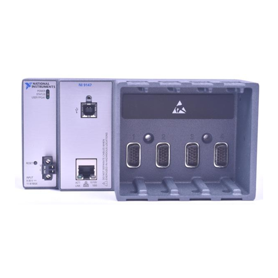
USER MANUAL
NI 9147
Ethernet Expansion Chassis for C Series Modules
This document describes the features of the NI 9147 and contains information about mounting
and operating the device.
RJ-45
Ethernet1
USB 2.0 Device Port
NI 9147
Contents
Configuring the NI 9147........................................................................................................... 2
Connecting the NI 9147 to the Host Computer or Network Using Ethernet.................... 2
Configuring Startup Options............................................................................................. 3
NI 9147 Features....................................................................................................................... 3
Ports and Connectors........................................................................................................ 3
Buttons.............................................................................................................................. 7
LEDs................................................................................................................................. 8
Chassis Grounding Screw............................................................................................... 10
Internal Real-Time Clock................................................................................................11
Battery............................................................................................................................. 11
Mounting the Device...............................................................................................................11
Dimensions......................................................................................................................12
Mounting Requirements..................................................................................................13
GigE
Xilinx Zynq-7000
MAC/PHY
All-Programmable SOC
XC7Z020
+
+
+
+
512 MB
NAND Flash
256 MB
DDR3
Hardware
Data
Advertisement
Table of Contents

Subscribe to Our Youtube Channel
Related Manuals for National Instruments NI 9147


Summary of Contents for National Instruments NI 9147
-
Page 1: Table Of Contents
USER MANUAL NI 9147 Ethernet Expansion Chassis for C Series Modules This document describes the features of the NI 9147 and contains information about mounting and operating the device. GigE 512 MB RJ-45 Xilinx Zynq-7000 NAND Flash Ethernet1 MAC/PHY XC7Z020... -
Page 2: Configuring The Ni 9147
Worldwide Support and Services.................... 19 Configuring the NI 9147 You can connect the NI 9147 to a host computer or network and configure the startup options using the USB device port or the RJ-45 Gigabit Ethernet port 1. Refer to the getting started guide on ni.com/manuals... -
Page 3: Configuring Startup Options
FPGA. All FPGA I/O lines are tri-stated after a reset, and will enter predefined states once loaded. Enable Secure Rebooting the NI 9147 with this setting on starts sshd on the NI 9147. Shell (SSH) Starting sshd enables logins over SSH, an encrypted communication Logins protocol. - Page 4 3. Power Connector RJ-45 Gigabit Ethernet Port The NI 9147 has one tri-speed RJ-45 Gigabit Ethernet port. By default, the Ethernet port is enabled and configured to obtain an IP address automatically. The Ethernet port can be configured in MAX.
- Page 5 Related Information Ethernet LED Indicators on page 10 Power Connector The NI 9147 has a power connector to which you can connect a power supply. The following table shows the pinout for the power connector. Table 4. Power Connector Pinout Pinout...
- Page 6 Caution Do not hot-swap USB devices while the NI 9147 is in a hazardous location or connected to high voltages. If the NI 9147 is not in a hazardous location, you can connect and disconnect USB devices without affecting operation.
-
Page 7: Buttons
Console Out. Hold the RESET button again for 5 seconds to boot the controller into safe mode, enable Console Out, and reset network adapters to default settings. NI 9147 User Manual | © National Instruments | 7... -
Page 8: Leds
System Reset The following figure shows the reset behavior of the NI 9147. Figure 3. Reset Button Behavior Press and hold RESET button for < 5 s Press and hold RESET button for ≥ 5 s Safe Mode • FPGA Startup App disabled Run Mode Press and hold RESET button for <... - Page 9 Measurement & Automation Explorer (MAX) Help for information about installing software on the NI 9147. Blinks three times The NI 9147 is in user-directed safe mode, or the NI 9147 is in install and pauses mode to indicate that software is currently being installed.
-
Page 10: Chassis Grounding Screw
Figure 5. NI 9147 Chassis Grounding Screw 1. Chassis grounding screw For EMC compliance, you must connect the NI 9147 to earth ground through the chassis ground screw. Use wire that is 1.31 mm (16 AWG) solid copper wire with a maximum length of 1.5 m (5 ft). -
Page 11: Internal Real-Time Clock
The NI 9147 contains a lithium cell battery that stores the system clock information when the NI 9147 is powered off. There is only a slight drain on the battery when power is applied to the NI 9147 power connector. The rate at which the battery drains when power is disconnected depends on the ambient storage temperature. -
Page 12: Dimensions
You can also mount the NI 9147 in other orientations, on a nonmetallic surface, on a 35-mm DIN rail, on a desktop, or in a rack. Mounting the NI 9147 in these or other configurations can reduce the maximum allowable ambient temperature and can affect the typical accuracy of modules in the NI 9147. -
Page 13: Mounting Requirements
Mounting Requirements Your installation must meet the following requirements for cooling and cabling clearance. Allow 25.4 mm (1.00 in.) on the top and the bottom of the NI 9147 for air circulation, as shown in the following figure. Figure 9. NI 9147 Cooling Dimensions 25.4 mm (1.00 in.) -
Page 14: Mounting The Device Directly On A Flat Surface
1. Location for measuring the ambient temperature Mounting the Device Directly on a Flat Surface For environments with high shock and vibration, NI recommends mounting the NI 9147 directly on a flat, rigid surface using the mounting holes in the NI 9147. What to Use •... -
Page 15: Mounting The Device On A Panel
Align the NI 9147 on the surface. Fasten the NI 9147 to the surface using the M4 or number 8 screws appropriate for the surface. Tighten the screws to a maximum torque of 1.3 N · m (11.5 lb · in.). - Page 16 Align the NI 9147 and the panel mounting plate. Fasten the panel mounting plate to the NI 9147 using the screwdriver and M5 or number 10 screws. NI provides these screws with the panel mounting kit. Tighten the screws to a maximum torque of 1.3 N ·...
-
Page 17: Mounting The Device On A Din Rail
(1.25 in.) (3.47 in.) 63.5 mm (2.50 in.) Mounting the Device on a DIN Rail You can use the NI DIN rail mounting kit to mount the NI 9147 on a standard 35-mm DIN rail. What to Use • NI 9147 •... -
Page 18: Mounting The Device On A Rack
Fasten the DIN rail kit to the NI 9147 using the screwdriver and M4 × 25 flathead screws. NI provides these screws with the DIN rail mounting kit. Tighten the screws to a maximum torque of 1.3 N · m (11.5 lb · in.). -
Page 19: Worldwide Support And Services
Align the brackets with the mounting holes on the ends of the NI 9147. Use the screwdriver to tighten the captive screws on the end of the brackets. Worldwide Support and Services The NI website is your complete resource for technical support. At ni.com/support, you have access to everything from troubleshooting and application development self-help resources to email and phone assistance from NI Application Engineers. - Page 20 CONTAINED HEREIN AND SHALL NOT BE LIABLE FOR ANY ERRORS. U.S. Government Customers: The data contained in this manual was developed at private expense and is subject to the applicable limited rights and restricted data rights as set forth in FAR 52.227-14, DFAR 252.227-7014, and DFAR 252.227-7015. © 2015—2016 National Instruments. All rights reserved. 376510B-01 Feb16...
Need help?
Do you have a question about the NI 9147 and is the answer not in the manual?
Questions and answers