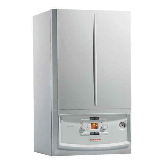
Immergas VICTRIX 24 TT 1E Instruction And Warning Book
Hide thumbs
Also See for VICTRIX 24 TT 1E:
- Instruction manual (40 pages) ,
- Instruction and warning book (44 pages)
Table of Contents
Advertisement
Advertisement
Table of Contents
Troubleshooting

Subscribe to Our Youtube Channel
Related Manuals for Immergas VICTRIX 24 TT 1E


Summary of Contents for Immergas VICTRIX 24 TT 1E
- Page 1 VICTRIX 24 TT 1E Instruction and warning book...
- Page 3 Read the following pages carefully: you will be able to draw useful suggestions regarding the correct use of the appliance, the respect of which, will confirm your satisfaction for the Immergas product.
-
Page 4: Table Of Contents
1.9 External temperature probe (Optional)... 9 2.10 Anti-freeze protection........25 3.9 Fast calibration..........30 1.10 Immergas flue systems........10 2.11 Case cleaning............. 25 3.10 Flue test.............. 31 1.11 Tables of resistance factors and equivalent 2.12 Decommissioning. -
Page 5: Boiler Installation
The place of installation of the appliance and • Installation regulations: relative Immergas accessories must have suitable - this boiler can be installed outdoors in a features (technical and structural) such to allow partially protected area. A partially protect-... -
Page 6: Main Dimensions
The materials used for the central heating circuit of Immergas boilers withstand ethylene and propylene glycol based antifreeze liquids (if the mixtures are prepared perfectly). For life and possible disposal, follow the sup-... -
Page 7: Boiler Connection Unit
1.4 BOILER CONNECTION UNIT. Fuel gas quality. The appliance has been de- Attention: Immergas declines all liability in the The connection unit, which is composed of all the signed to operate with combustible gas free of event of damage caused by the inclusion of auto- required accessories to connect the appliance's impurities;... -
Page 8: Electric Connection
(with adjustable temperature). with extreme precision and therefore with Attention: Immergas S.p.A. declines any respon- Execute connection to terminal boards 14 and 15, evident saving in running costs. The CAR sibility for damage or physical injury caused by eliminating jumper X70 (Fig. -
Page 9: External Temperature Probe (Optional)
Immergas chrono-thermostats. The correlation between system flow temperature and external temperature is determined by the position of the central heating selector switch on... -
Page 10: Immergas Flue Systems
Attention: the boiler must be installed ex- element in order to ensure sealing efficiency of clusively with an original Immergas “Green the coupling. Range” inspectionable air intake device and Attention: if the exhaust terminal and/or... - Page 11 Resistance Equivalent length Equivalent Equivalent length Equivalent length TYPE OF DUCT Factor in m of concentric length in metres in metres of pipe in m of concentric pipe Ø 60/100 of pipe Ø 80 Ø 60 pipe Ø 80/125 Intake m 7.3 Concentric pipe Ø...
-
Page 12: Area
(B53) or ustrade (W=0 if the balustrade is open). via an Immergas ducting system (B53). • Configuration without cover kit in a partially The technical regulations in force must be protected location (type C boiler) respected. -
Page 13: Concentric Horizontal Kit Installation
100. In this case the special extensions must subtracted. In this case the special extensions be requested. must be requested. Immergas also provides a Ø 60/100 simplified terminal, which in combination with its ex- tension kits allows you to reach a maximum extension of 11.9 metres. -
Page 14: Concentric Vertical Kit Installation
1.14 CONCENTRIC VERTICAL KIT (3) concentric terminal pipe with the male end Ø 80/125 concentric terminal pipe with the male INSTALLATION. (5) (smooth) into the flange (2) up to the stop; side (smooth) to the female side of the adapter (1) Type C configuration, sealed chamber and making sure that the wall sealing plate has been (with lip gaskets) up to the end stop;... -
Page 15: Separator Kit Installation
1.15 SEPARATOR KIT INSTALLATION. • Installation clearances (Fig. 1-22). The mini- Type C configuration, sealed chamber and mum installation clearance measurements of fan assisted. the Ø 80/80 separator terminal kit have been stated in some limit conditions. Separator kit Ø 80/80. This kit allows air to come • Extensions for separator kit Ø 80/80. The in from outside the building and the fumes to exit maximum vertical straight length (without from the chimney or flue through divided flue... -
Page 16: Adaptor C9 Kit Installation
- Mount the cover (A) complete with adaptor (1) To determine the C93 flue system in configu- This kit allows to install an Immergas boiler in and caps (6) on the wall and assemble the flue rations other than that described (Fig. 1-26) configuration "C93", achieving the combustion... -
Page 17: Ducting Of Flues Or Technical Slots
Ø 80 flexible “Green Range” ducting systems must OPEN CHAMBER AND FORCED of the appliances attached to the same multiple only be used for domestic use and with Immergas DRAUGHT FOR INDOORS. flues or combined flues, must not differ by more condensing boilers. -
Page 18: Water Treatment System Filling
- Check the maximum hardness and quantity activate the warranty of Immergas. The test certif- re-activated systems. of filling water referring to the graphics (Fig. -
Page 19: Circulation Pump
By-pass Regulation (part. 24 Fig. 1-30). The flow rate high for each zone, Immergas supplies boiler leaves the factory with the by-pass open. zone system kits by request. -
Page 20: Boiler Components
1.28 BOILER COMPONENTS. 1-30 Key: 14 - Flue probe 1 - System filling valve 15 - Burner cover 2 - System draining valve 16 - Safety flow probe 3 - DHW heat exchanger 17 - Condensation module 4 - Gas valve 18 - Fan 5 - Domestic hot water probe 19 - System pressure switch... -
Page 21: Use And Maintenance Instructions
• Attention: the use of components involving use of Immergas. We recommend stipulating a yearly of electrical power requires some fundamental cleaning and maintenance contract with your rules to be observed: zone Immergas Authorised After-sales Service. -
Page 22: Using The Boiler
2.4 USING THE BOILER. temperature can be modified by selecting the Before ignition make sure the heating system functioning curve via the selector switch (4) is filled with water and that the manometer (7) (or on the CAR control panel, if connected indicates a pressure of 1 ÷... -
Page 23: Troubleshooting
(see relative thermostat (optional) blocks. instructions sheet). (1). Burner power limi- Should flue high temperature be detected, the boiler reduces power tation supplied so as not to damage it. (1) If the block or anomaly persists, contact an authorised company (e.g. Immergas Technical After-Sales Service). (2) The anomaly can only be verified in the list of errors in the “Information” menu... - Page 24 If normal conditions are restored the boiler system. restarts without having to be reset Block - maximum no. of The maximum number of software errors possible has been Press the Reset button (1) software errors reached. General block A boiler anomaly has been detected Press the Reset button (1) (1) If the block or anomaly persists, contact an authorised company (e.g. Immergas Technical After-Sales Service). (2) The anomaly can only be verified in the list of errors in the “Information” menu...
-
Page 25: Information Menu
If the pressure falls below 1 bar (with the circuit Immergas Anti-freeze Kit in the boiler. In the cold) restore normal pressure via the valve located case of prolonged inactivity (second case), we at the bottom of the boiler (Fig. -
Page 26: Boiler Commissioning (Initial Check)
BOILER COMMISSIONING - switch the boiler on and check correct ignition; - check the production of domestic hot water; (INITIAL CHECK) - check the CO flow rate in the flue: - check sealing efficiency of water circuits; - maximum (100%) - check ventilation and/or aeration of the instal- To commission the boiler: lation room where provided. -
Page 27: Wiring Diagram
3.2 WIRING DIAGRAM. Connections 230 V Connections very low voltage... -
Page 28: Removable Memory
Amico Remoto remote control (CAR ), which out by an authorised company (e.g. Immergas Check that there are no residues of material must be connected to clamps 41 and 44 of the After-Sales Technical Assistance Service). -
Page 29: Converting The Boiler To Other Types Of Gas
The gas conversion operation must be carried icons: “summer”, “winter”, “stand-by” and the - nominal heat output calibration; out by an authorised company (e.g. Immergas operating temperature alternated with the cur- After-Sales Technical Assistance Service). - intermediate heat output ignition calibration;... -
Page 30: Adjusting The Air Gas Ratio
3.8 ADJUSTING THE AIR GAS RATIO 3.9 FAST CALIBRATION. At this stage the display features flashing icons: During complete calibration (par. 3.7), you can This function allows you to calibrate the boiler “summer”, “winter”, “stand-by”, “external probe”, modify the values of the air - gas ratio. automatically without requiring or giving the “solar probe”... -
Page 31: Flue Test
3.10 FLUE TEST. Check the ΔP between the test pressures (fig. 1-30 3.11 PROGRAMMING THE P.C.B. To define the value to set in the ”flue length” Ref. 13), in compliance with the values indicated The boiler is prepared for possible programming “F0”... - Page 32 Parameter Description Range Default Parameter 750 ÷ 1700 Min output The P.C.B. defines the operating mode and the boiler output according to the combi- nation of several parameters. The proper operating output of the appliance is defined According S0 ÷ 7375 Max output according to the combination of the parameters of menus “n”...
- Page 33 Parameter Description Range Default Parameter Central heating set point min- Defines the minimum flow temperature. 20 ÷ 50 °C imum temper- ature Central heating set point max- (t0+5) ÷ 85 Defines the maximum flow temperature. imum temper- °C ature Establishes the switch-off method in DHW mode. 1 and 3 Correlated: the boiler switches off according to the temperature set.
-
Page 34: Solar Panels Coupling Function
3.12 SOLAR PANELS COUPLING 3.16 RADIATORS ANTIFREEZE - Check ignition and operation. FUNCTION. FUNCTION. - Check correct calibration of the burner in The boiler is set-up to receive pre-heated water If the system return water is below 4°C, the boiler domestic hot water and central heating phases. -
Page 35: Casing Removal
3.20 CASING REMOVAL. • Front (Fig. 3-15c). To facilitate boiler maintenance the casing can 6) Loosen the two screws (g). be completely removed as follows: 7) Pull the front (f) slightly towards you. • Lower grid (Fig. 3-15a). 8) Release front (f) from pins (h) pulling it 1) Loosen the two screws (a);... - Page 36 • Control panel (Fig. 3-15d). • Sides (Fig. 3-15e). 9) Press the hooks on the side of the control 11) Loosen screws (k) of side fastening (j). panel (i). 12) Remove the sides by extracting them from 10) Tilt the control panel (i) towards you. their rear seat (Rif.
-
Page 37: Variable Heat Output
3.21 VARIABLE HEAT OUTPUT. in length. Gas flow rates refer to net heating value N.B.: the power data in the table has been ob- below a temperature of 15°C and at a pressure tained with intake-exhaust pipe measuring 0.5 m of 1013 mbar. -
Page 38: Technical Data
3.23 TECHNICAL DATA. Domestic hot water nominal heat input kW (kcal/h) 24,6 (21174) Central heating nominal heat input kW (kcal/h) 21,3 (18308) Minimum heat input kW (kcal/h) 3,1 (2630) Domestic hot water nominal heat output (useful) kW (kcal/h) 23,6 (20296) Central heating nominal heat output (useful) kW (kcal/h) 20,5 (17630) -
Page 39: Key For Data Nameplate
3.24 KEY FOR DATA NAMEPLATE. Cod. Md Sr N° Cod. PIN Type n min. max. n min. n max. Class CONDENSING N.B.: the technical data is provided on the data plate on the boiler Model Cod. Md Model code Sr N° Serial Number Check Cod. - Page 40 Follow us Immergas Italia immergas.com Immergas S.p.A. 42041 Brescello (RE) - Italy Tel. 0522.689011 Fax 0522.680617 Certified company ISO 9001...
Need help?
Do you have a question about the VICTRIX 24 TT 1E and is the answer not in the manual?
Questions and answers