Table of Contents
Advertisement
OPERATOR'S MANUAL
MODEL #100520
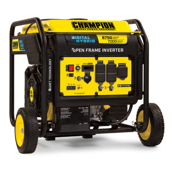
8750W PORTABLE
INVERTER GENERATOR
REGISTER YOUR PRODUCT ONLINE
at championpowerequipment.com
or visit championpowerequipment.com
SAVE THESE INSTRUCTIONS. This manual contains important safety precautions which should be read and understood before operating the product. Failure to do
so could result in serious injury. This manual should remain with the product.
Specifications, descriptions and illustrations in this manual are as accurate as known at the time of publication, but are subject to change without notice.
This product is rated in accordance with PGMA (Portable Generator Manufacturers' Association) standard ANSI/PGMA G300 (Safety and Performance of Portable
Generators).
Made in China - REV 20191230
Champion Power Equipment, Inc., Santa Fe Springs, CA USA
Advertisement
Table of Contents

Related Manuals for Champion 100520


Summary of Contents for Champion 100520
- Page 1 Specifications, descriptions and illustrations in this manual are as accurate as known at the time of publication, but are subject to change without notice. This product is rated in accordance with PGMA (Portable Generator Manufacturers’ Association) standard ANSI/PGMA G300 (Safety and Performance of Portable Generators). Made in China - REV 20191230 Champion Power Equipment, Inc., Santa Fe Springs, CA USA...
-
Page 2: Table Of Contents
TABLE Of CONTENTS 100520 - 8750W PORTABLE INVERTER GENERATOR TABLE Of CONTENTS Maintenance ..........Cleaning the Generator .......... Introduction ........... Changing the Engine Oil ......... -
Page 3: Introduction
100520 - 8750W PORTABLE INVERTER GENERATOR INTRODUCTION SAfETY DEfINITIONS Congratulations on your purchase of a Champion Power Equipment The purpose of safety symbols is to attract your attention to (CPE) product. CPE designs, builds, and supports all of our possible dangers. The safety symbols, and their explanations, products to strict specifications and guidelines. -
Page 4: Important Safety Instructions
DO NOT use electrical cords that are worn, damaged or frayed. recreational vehicle. Use only Champion electrical cords for proper application. DO NOT allow exhaust fumes to enter a confined area through DO NOT operate generator in wet weather. - Page 5 IMPORTANT SAfETY INSTRUCTIONS 100520 - 8750W PORTABLE INVERTER GENERATOR WARNING CAUTION Spark from removed spark plug wire can result in fire or Start the generator and allow the engine to stabilize before electrical shock. connecting electrical loads. Connect electrical equipment in the off position, and then turn When servicing the generator: them on for operation.
-
Page 6: Fuel Safety
IMPORTANT SAfETY INSTRUCTIONS 100520 - 8750W PORTABLE INVERTER GENERATOR fuel Safety When operating the generator: DO NOT move or tip the generator during operation. DANGER DO NOT tip the generator or allow fuel or oil to spill. GASOLINE AND GASOLINE VAPORS ARE HIGHLY When transporting or servicing the generator: FLAMMABLE AND EXPLOSIVE. -
Page 7: Safety Labels
Fuel UNLEADED FUEL ONLY. Minimum octane This artwork belongs to Champion Power Equipment. The contents are confidential and privileged and shall not be disclosed to or used by or for rating of 85. Maximum 10% ethanol. outside parties without the explicit consent of Champion Power Equipment. -
Page 8: Safety Symbols
IMPORTANT SAfETY INSTRUCTIONS 100520 - 8750W PORTABLE INVERTER GENERATOR Safety Symbols Some of the following symbols may be used on this product. Please study them and learn their meaning. Proper interpretation of these symbols will allow you to more safely operate the product. -
Page 9: Operation Symbols
IMPORTANT SAfETY INSTRUCTIONS 100520 - 8750W PORTABLE INVERTER GENERATOR Operation Symbols Some of the following symbols may be used on this product. Please study them and learn their meaning. Proper interpretation of these symbols will allow you to more safely operate the product. -
Page 10: Quick Start Label Symbols
Starting the Engine Stopping the Engine This artwork belongs to Champion Power Equipment. The contents are confidential and privileged and shall not be disclosed to or used by or for 1. Turn off and unplug all connected electrical loads. outside parties without the explicit consent of Champion Power Equipment. -
Page 11: Controls And Features
CONTROLS AND fEATURES 100520 - 8750W PORTABLE INVERTER GENERATOR CONTROLS AND fEATURES Read this operator’s manual before operating your generator. Familiarize yourself with the location and function of the controls and features. Save this manual for future reference. Generator 1. Reversal Valve 8. -
Page 12: Control Panel
CONTROLS AND fEATURES 100520 - 8750W PORTABLE INVERTER GENERATOR Control Panel 1. Ignition Switch – Used to put in START mode or STOP the RECEPTACLES generator. 12V DC, 8 Amp (Automotive) 2. Economy Mode Switch – Enables/disables automatic idle May be used to supply electrical power for control. -
Page 13: Intelligauge
CONTROLS AND fEATURES 100520 - 8750W PORTABLE INVERTER GENERATOR Intelligauge Four mode digital meter for displaying voltage, frequency (hertz), run time, and total run time. The LCD displays each mode by pressing the button below the display. MODE BUTTON MODE DESCRIPTION Output voltage of the generator. -
Page 14: Fcc Statement
CONTROLS AND fEATURES 100520 - 8750W PORTABLE INVERTER GENERATOR fCC Statement Parts Included 1. This device complies with Part 15 of the FCC Rules. Operation Accessories is subject to the following two conditions: Flexible Oil Funnel ..............1 1a. This device may not cause harmful interference. -
Page 15: Assembly
ASSEMBLY 100520 - 8750W PORTABLE INVERTER GENERATOR ASSEMBLY Install the Wheel Kit Your generator requires some assembly. This unit ships from our CAUTION factory without oil. It must be properly serviced with fuel and oil before operation. The wheel kit is not intended for over-the-road use. -
Page 16: Connect The Battery
ASSEMBLY 100520 - 8750W PORTABLE INVERTER GENERATOR Install the Handle NOTICE 1. Place the handle (F) over the mounting channel on the frame. The generator rotor has a sealed, pre-lubricated ball bearing 2. Secure the handle to the frame using the four flange that requires no additional lubrication for the life of the bearing. -
Page 17: Add Fuel
ASSEMBLY 100520 - 8750W PORTABLE INVERTER GENERATOR NOTICE Once oil has been added, a visual check should show oil about 1-2 threads from running out of the fill hole. When using the dipstick to check oil level, DO NOT screw in the dipstick while checking. -
Page 18: Grounding
OPERATION 100520 - 8750W PORTABLE INVERTER GENERATOR – Electrical devices that require a grounded receptacle pin WARNING connection will not function if the receptacle ground pin is not functional. Pouring gasoline too fast through the fuel screen may result... -
Page 19: Surge Protection
OPERATION 100520 - 8750W PORTABLE INVERTER GENERATOR Electric Start WARNING 1. Press and hold the ignition switch to the “START” position. During operation the muffler and exhaust fumes will become Release as the engine begins to start. If the engine fails to hot. -
Page 20: Connecting Electrical Loads
OPERATION 100520 - 8750W PORTABLE INVERTER GENERATOR 2. Pull choke button to “CHOKE” position. NOTICE For gasoline restarts with hot engine in hot ambient temperature > 86°F (30°C), keep the choke in “CHOKE” position for only 1 pull of the recoil starter. After first pull, press choke to the “RUN”... -
Page 21: Do Not Overload Generator
OPERATION 100520 - 8750W PORTABLE INVERTER GENERATOR 5. Plug in and turn on the next item. WARNING 6. Allow the engine to stabilize. Connecting a generator to your electric utility company’s 7. Repeat steps 5-6 for each additional item. -
Page 22: 12V Dc Automotive Style Outlet
OPERATION 100520 - 8750W PORTABLE INVERTER GENERATOR Battery Charging 1. Before connecting the battery charging cable (included) to a battery that is installed in a vehicle, disconnect the vehicle battery ground cable from the negative (–) battery terminal. 2. Plug the battery charging cable into the 12V DC receptacle of the generator. -
Page 23: Operation At High Altitude
OPERATION 100520 - 8750W PORTABLE INVERTER GENERATOR In order to select the correct high altitude main jet it is necessary to identify the carburetor model. For this purpose, a code is stamped on the side of the carburetor. Select the correct high altitude jet part number corresponding to the carburetor code found on your particular carburetor. -
Page 24: Maintenance
MAINTENANCE 100520 - 8750W PORTABLE INVERTER GENERATOR MAINTENANCE Changing the Engine Oil Change oil when the engine is warm. Refer to the oil specification Make certain that the generator is kept clean and stored properly. to select the proper grade for your operating environment. -
Page 25: Cleaning The Air Filter
MAINTENANCE 100520 - 8750W PORTABLE INVERTER GENERATOR 3. Inspect the electrode on the plug. It must be clean and not 4. Carefully remove the carbon deposits from the spark arrestor worn to produce the spark required for ignition. screen with a wire brush. -
Page 26: Maintenance Schedule
STORAGE 100520 - 8750W PORTABLE INVERTER GENERATOR STORAGE Maintenance Schedule Follow the service intervals indicated in the following maintenance DANGER schedule. Service your generator more frequently when operating in adverse Gasoline vapors are highly flammable and extremely explosive. conditions. -
Page 27: Long Term Storage (Over 1 Year)
STORAGE 100520 - 8750W PORTABLE INVERTER GENERATOR Removing from Storage If the generator has been improperly stored for a long period of time with gasoline in the gasoline tank and/or carburetor, all fuel must be drained and the carburetor must be thoroughly cleaned. -
Page 28: Specifications
SPECIfICATIONS 100520 - 8750W PORTABLE INVERTER GENERATOR SPECIfICATIONS Oil Specifications DO NOT OVERFILL. Generator Specifications Type ..........*See chart below Generator Model ......... . . -
Page 29: Parts Diagram
SPECIfICATIONS 100520 - 8750W PORTABLE INVERTER GENERATOR Parts Diagram... -
Page 30: Parts List
SPECIfICATIONS 100520 - 8750W PORTABLE INVERTER GENERATOR Parts List Part Number Description Qty. Part Number Description Qty. R420DI000FB-CMP303 Engine, 420cc 33 51005HY9X0310-0000 Vibration Mount, Frame Flange Nut, M10 x 1.25, 18100-Y9X0411-H300 Muffler Assembly 34 90306-1000-31 Blue White Zinc 18013-Y9X0120-H300 Muffler Shield Flange Bolt, M10 x 1.25 x... - Page 31 SPECIfICATIONS 100520 - 8750W PORTABLE INVERTER GENERATOR Part Number Description Qty. Part Number Description Qty. 93 30700-YBE0110-0000 Vibration Mount, Support Ignitor 63 51014HY9X0110-0000 Leg, 94 35160-Y0G0110-0000 Economy Switch Flange Bolt, M6 x 20, Corrugated Pipe, 64 90001-0620-03 95 90697-Y9X0110-0000 Black Zinc Ø40 x 250...
-
Page 32: Engine Parts Diagram
SPECIfICATIONS 100520 - 8750W PORTABLE INVERTER GENERATOR Engine Parts Diagram... -
Page 33: Engine Parts List
SPECIfICATIONS 100520 - 8750W PORTABLE INVERTER GENERATOR Engine Parts List Part Number Description Qty. Part Number Description Qty. Cylinder Head Cover Bolt 34 12105-Z080110-0000 Valve Spring Seat 12032-Z080110-0100 Subassembly, Blue White 35 12103-Z080110-0000 Valve Spring Zinc Valve Spring Retainer, 36 12112-Z080110-0000... - Page 34 SPECIfICATIONS 100520 - 8750W PORTABLE INVERTER GENERATOR Part Number Description Qty. Part Number Description Qty. 67 90502-0812-00 Pin, Ø8 x 12 16161-Z320310-0000 Main Jet, Standard Crankcase Cover Main Jet, Altitude 3000- 68 11411-Z980110-0BA0 16161-Z320410-0000 Assembly 6000 Feet Oil Dipstick Subassembly,...
-
Page 35: Wiring Diagram
SPECIfICATIONS 100520 - 8750W PORTABLE INVERTER GENERATOR Wiring Diagram... -
Page 36: Troubleshooting
TROUBLESHOOTING 100520 - 8750W PORTABLE INVERTER GENERATOR TROUBLESHOOTING Problem Cause Solution No fuel. Add fuel. Faulty spark plug. Clean and adjust spark plug or replace. Fill crankcase to the proper level. Low oil level. Place generator on a flat, level surface. -
Page 37: Warranty
To complete registration you will need to include a copy of the – Problems caused by parts that are not original Champion purchase receipt as proof of original purchase. Proof of purchase Power Equipment parts. - Page 38 THE UNITED STATES ENVIRONMENTAL PROTECTION AGENCY (U.S. EPA) AND THE CALIFORNIA AIR RESOURCES BOARD (CARB) EMISSION CONTROL SYSTEM WARRANTY Your Champion Power Equipment (CPE) engine complies with both the U.S. EPA and state of California Air Resources Board (CARB) emissions regulations.
- Page 39 EMISSION CONTROL SYSTEM WARRANTY The following are specific provisions relative to your Emission Control System (ECS) Warranty Coverage. 1. APPLICABILITY: This warranty shall apply to 1995 and later model year California small off-road engines (SORE) (for other states, 1997 and later model year engines). The ECS Warranty Period shall begin on the date the new engine or equipment is delivered to its original, end-use purchaser, and shall continue for 24 consecutive months thereafter.
- Page 40 You must take your CPE engine or the product on which it is installed, along with your warranty registration card or other proof of original purchase date, at your expense, to any Champion Power Equipment dealer who is authorized by Champion Power Equipment, Inc. to sell and service that CPE product during his normal business hours.
Need help?
Do you have a question about the 100520 and is the answer not in the manual?
Questions and answers