Advertisement
•
battery status control
•
works with PSB 27,6V power supply units
•
LED indication
•
FAC technical output indicating AC power
collapse – OC and relay type
1. Technical description.
1.1 General description
MPSB24 automation module is intended for indicating the operating status of buffer power supplies PSB 27,6V type.
The PCB board features LEDs that indicate PSU operating status (presence of AC voltage, presence of DC voltage,
battery voltage). The module is also equipped with technical outputs of: AC power loss, PSU failure, low battery
voltage.
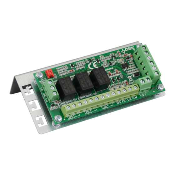
1.1. Description of the module's components and connectors (fig1, tab.1)
Table 1
Element
no.
[1]
LED indicating presence of 230VAC voltage
[2]
LED indicating presence of DC voltage at the PSU output
[3]
LED indicating correct battery voltage
[4]
FAC- technical output indicating AC absence – relay type
[5]
FAC- technical output indicating AC absence – OC type
[6]
FPS- output indicating DC absence/PSU failure - OC type
[7]
FLB- output indicating low battery voltage - OC type
[8]
Indication connector
[9]
+BAT- battery connector
[10]
+V –27,6V supply
MPSB24
v.1.0
PSB 27,6V automation module
Edition: I (08 Mar2012)
Features:
• FPS technical output indicating power supply
module's failure
• FLB technical output indicating low battery
voltage
Description
Fig. 1. The view of the module.
1
EN
Advertisement
Table of Contents

Related Manuals for Pulsar MPSB24


Summary of Contents for Pulsar MPSB24
- Page 1 1. Technical description. 1.1 General description MPSB24 automation module is intended for indicating the operating status of buffer power supplies PSB 27,6V type. The PCB board features LEDs that indicate PSU operating status (presence of AC voltage, presence of DC voltage, battery voltage).
- Page 2 1.2 Specifications: - electrical specifications (tab.2) - mechanical specifications (tab.3) Table 2. Supply voltage 27,6V DC Current consumption 30mA max. Voltage of low battery indication U<23V +/- 3% Technical outputs: - FAC; output indicating AC power - relay type: 1A@ 30VDC/50VAC, time lag: approx. 10s. failure - OC type, 50mA max., normal status: L (0V) level, failure: hi-Z level, time lag: 10s.
- Page 3 The shock protection circuit shall be performed with a particular care, i.e. the yellow and green wire coat of the power cable shall stick to one side of the ‘PE’ terminal. Using the PSU without a properly made and fully operational shock protection circuit is UNACCEPTABLE! It can cause a device failure or an electric shock.
- Page 4 WEEE separately. GENERAL WARRANTY CONDITIONS 1. Pulsar K. Bogusz Sp.j. (the manufacturer) grants a two-year warranty for the equipment, starting from the initial product date of purchase placed on the receipt. 2. If a purchase proof is missing, a three-year warranty period is counted from the device’s production date.
Need help?
Do you have a question about the MPSB24 and is the answer not in the manual?
Questions and answers