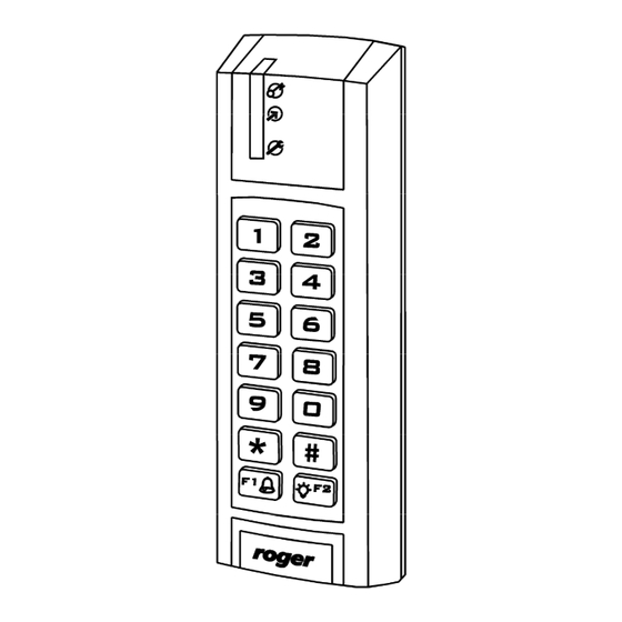
Roger PR311SE Installation Manual
Hide thumbs
Also See for PR311SE:
- Function manual (43 pages) ,
- Installation manual (16 pages) ,
- Installation manual (16 pages)
Summary of Contents for Roger PR311SE
- Page 1 Roger Access Control System Installation guide for PR311SE/PR311SE-BK Access Controllers Firmware version: 1.16.xxxx Document version: Rev. F...
-
Page 2: Table Of Contents
Contents 1. Introduction ......................... 3 1.1 This manual ........................3 1.2 Typing conventions ......................3 2. Description and specification ..................4 3. Installation ........................5 3.1 Wires and connection diagram ................... 5 3.2 LED indicators ........................6 3.3 Power supply ........................7 3.4 Connection of door locking device .................. -
Page 3: Introduction
If PR311SE and PR311SE-BK controllers are not clearly distinguished in particular paragraph, then information specified for PR311SE are also valid for PR311SE-BK. But if PR311SE-BK name is used in particular paragraph then the information concerns only that specific type of controller. -
Page 4: Description And Specification
Additional external reader of PRT series (Roger) operating in RACS Clock&Data mode can be connected to PR311SE if it is required to provide access control at both sides of the door. PR311SE can be installed both outdoors and indoors and does not require special protection against rain and moisture. -
Page 5: Installation
3. I NSTALLATION 3.1 Wires and connection diagram PR311SE controller is equipped with 0,5m connection cable including following wires. Table 2. Wires Name Colour Description +12V Positive power supply contact, 12V DC Black Negative power supply contact and reference potential for RS485 communication bus, input lines and RACS Clock&Data bus... -
Page 6: Led Indicators
Fig. 1 PR311SE connection diagram 3.2 LED indicators PR311SE controller is equipped with 3 LED indicators. Their functions and colours are specified in table 3 below. Functioning of LEDs can be verified by means of included MASTER card. Page 6 of 15... -
Page 7: Power Supply
The power supply can be provided by means of power supply unit PS10 or PS20, which are available in Roger offer. The power supply units can be connected to backup battery in order to ensure operation of access control in case of power failure. -
Page 8: Connection Of External Reader And/Or Extension Module
REL1 relay output is door unlock. 3.6.1 Inputs All inputs (IN1-IN3) of PR311SE have identical electric structure and can be configured as NO or NC lines. The NO input is triggered by shorting it to supply minus (GND) while the NC input must be normally shorted to supply minus (GND) and it becomes triggered when connection with ground is discontinued. - Page 9 Fig. 3 PR311SE controller with standard enclosure base Fig. 4 PR311SE controller with additional enclosure base Page 9 of 15...
-
Page 10: Installation Guidelines
· In case of installation on rough surface (porous) it is recommended to use metal spacer AX-1 (Roger). The spacer can be also used as electromagnetic screen, which prevents cross interferences of controllers/readers. Installation of AX-1 may result in reduction of reading distance by approx. -
Page 11: Configuration
4.1.1 Setting the address during firmware update (Fixed ID) FixedID can be set during update of the controller firmware by means of ROGER ISP software. Prior to firmware upload, Roger ISP software offers the possibility to set Fixed ID address in range of 00..99. -
Page 12: Memory Reset Procedure
· In case of PRT311SE-BK connect PRT series reader with keypad (e.g. PRT12LT) to CLK and DTA lines and execute further steps by means of that reader. In case of PR311SE, which is equipped with keypad, use controller keypad in further steps ·... -
Page 13: Controller Programming
(e.g. UT-2USB, RUD-1, UT- 4DR). PR Master software is available at www.roger.pl. · By means of command entered with keypad (in case of PR311SE-BK it is required to connect any PRT series reader with keypad, e.g. PRT12LT). - Page 14 Fig. 5 Location of FDM and RST contacts inside the enclosure of PR311SE controller · Reset the device (place and remove jumper on RST contacts or switch power off/on) · Start RogerISP software and select communication port (in case of RUD-1 select RS-485).
-
Page 15: Ordering Information
5. O RDERING INFORMATION Table 4. Ordering information PR311SE Access controller of standard PRxx1 series with built-in EM 125 kHz (UNIQUE) card reade, with keypad and with connection cable PR311SE- Access controller of standard PRxx1 series with built-in EM 125 kHz (UNIQUE) card...


Need help?
Do you have a question about the PR311SE and is the answer not in the manual?
Questions and answers