Table of Contents
Advertisement
Available languages
Available languages
Quick Links
General Safety Instructions:
READ SAFETY INSTRUCTIONS
Servicing:
These products are not customer serviceable. TDK-Lambda and their authorised agents
only are permitted to carry out repairs.
Critical Components:
These products are not authorised for use as critical components in nuclear control systems,
life support systems or equipment for use in hazardous environments without the express
written approval of the Managing Director of TDK-Lambda EMEA.
Product Usage:
These products are designed for use within a host equipment which restricts access to
authorised competent personnel.
This product is a component power supply and is only to be installed by qualified persons
within other equipment and must not be operated as a stand-alone product.
This product is for sale to business to business customers and can be obtained via
distribution channels. It is not intended for sale to end users.
This product is a component power supply and complies with the EMC directive. The
EMC performance of a component power supply will be affected by the final installation,
compliance to the stated EMC standards and conformance to the EMC Directive must be
confirmed after installation by the final equipment manufacturer.
For guidance with respect to test conditions please visit our website at https://emea.tdk-
lambda.com/EMC_guidance or contact your local TDK-Lambda sales office.
Environmental:
These products are IPX0, and therefore chemicals/solvents, cleaning agents and other
liquids must not be used.
Environment:
This power supply is a switch mode power supply for use in applications within a Pollution
Degree 2, overvoltage category II environment. Material Group IIIb PCB's are used within it.
Output Loading:
The output power taken from the power supply must not exceed the rating stated on the
power supply label, except as stated in the product limitations in this handbook.
Input Parameters:
This product must be operated within the input parameters stated in the product limitations
in this handbook.
1
Advertisement
Table of Contents

Related Manuals for TDK-Lambda FPS-T1U


Summary of Contents for TDK-Lambda FPS-T1U
- Page 1 General Safety Instructions: READ SAFETY INSTRUCTIONS Servicing: These products are not customer serviceable. TDK-Lambda and their authorised agents only are permitted to carry out repairs. Critical Components: These products are not authorised for use as critical components in nuclear control systems, life support systems or equipment for use in hazardous environments without the express written approval of the Managing Director of TDK-Lambda EMEA.
-
Page 2: Risk Of Electric Shock
In case of internal defect, the unit must be returned to TDK-Lambda or one of their authorised agents. A suitable mechanical, electrical and fire enclosure must be provided by the end use equipment for mechanical, electric shock and fire hazard protection. -
Page 3: Hot Surface
B) Reduced Air Flow - Installation of the equipment in a rack should be such that the amount of air flow required for safe operation of the equipment is not compromised. C) Mechanical Loading - Mounting of the equipment in the rack should be such that a hazardous condition is not achieved due to uneven mechanical loading. -
Page 4: Allgemeine Sicherheitsvorschriften
Allgemeine Sicherheitsvorschriften: LESEN SIE DIE SICHERHEITSVORSCHRIFTEN Wartung: Diese Produkte können nicht durch den Kunden gewartet werden. Nur TDK-Lambda und deren zugelassene Vertriebshändler sind zur Durchführung von Reparaturen berechtigt. Kritische Komponenten: Diese Produkte sind nicht für die Verwendung als kritische Komponenten in nuklearen Kontrollsystemen, Lebenserhaltungssystemen oder Geräten in gefährlichen Umgebungen... - Page 5 Schutzerde angeschlossen sein. Eine interne Sicherung schützt das Gerät und darf durch den Benutzer nicht ausgetauscht werden. Im Fall von internen Defekten muss das Gerät an TDK-Lambda oder einen der autorisierten Vertriebshändler zurückgeschickt werden. Ein geeignetes mechanisches, elektrisches und brandgeschütztes Gehäuse muss als Schutz vor der Gefahr von mechanischen Risiken, Stromschlägen und Brandschutz in...
- Page 6 Power Supplies for Build-in dürfen die Modulanschlüsse für den Benutzer nicht zugänglich sein. Trennvorrichtung: Eine geeignete Trennvorrichtung muss in die Verkabelung der Gebäudeinstallation integriert werden. Weitere Einzelheiten finden Sie im Benutzerhandbuch des jeweiligen Modells. Sicherheitshinweise für die Gestellmontage: A) Erhöhte Betriebsumgebung - Wenn das Gerät in einem geschlossenen oder mehrteiligen Gestell installiert wird, kann die Betriebsumgebungstemperatur der Gestellumgebung höher sein als die Raumtemperatur.
-
Page 7: Consignes Générales De Sécurité
Consignes générales de sécurité: LIRE LES CONSIGNES DE SECURITE Entretien: Ces produits ne peuvent pas être réparés par l’utilisateur. Seuls, TDK-Lambda et ses agents agréés sont autorisés à effectuer des réparations. Composants critiques: Ces produits ne doivent pas être utilisés en tant que composants critiques dans des systèmes de commande nucléaire, dans des systèmes de sauvetage ou dans des équipements utilisés... - Page 8 être remplacé par l'utilisateur. En cas de défaut interne, le module doit être renvoyé à TDK-Lambda ou l'un de ses agents agréés. Une enceinte appropriée doit être prévue par l'utilisateur final pour assurer la protection...
- Page 9 Energies dangereuses: Certains modules peuvent générer une énergie dangereuse (240 VA) selon le réglage de tension de sortie. Le fabricant de l'équipement final doit assurer la protection des techniciens d'entretien contre un contact involontaire avec les bornes de sortie de ces modules.
-
Page 10: Norme Generali Di Sicurezza
Manutenzione: Il cliente non può eseguire alcuna manutenzione su questi prodotti. L'esecuzione delle eventuali riparazioni è consentita solo a TDK-Lambda e ai suoi agenti autorizzati. Componenti critici: Non si autorizza l'uso di questi prodotti come componenti critici all'interno di sistemi... - Page 11 EMC dovranno essere confermata dopo l'installazione dell'alimentatore da parte del produttore dell'apparecchiatura finale. Per indicazioni riguardanti le condizioni di test si prega di visitare il nostro sito web all'indirizzo https:// emea.tdk-lambda.com/EMC_guidance o contattare l'ufficio vendite TDK-Lambda locale. Condizioni ambientali: Questi prodotti sono classificati come IPX0, dunque non devono essere utilizzati sostanze chimiche/solventi, prodotti per la pulizia o liquidi di altra natura.
- Page 12 CA. Un fusibile interno protegge l'unità e non deve essere sostituito dall'utente. Nell'eventualità di un difetto interno, restituire l'unità a TDK-Lambda o a uno dei suoi agenti autorizzati. L'apparecchiatura finale deve includere una recinzione meccanica, elettrica e antincendio per proteggere dai pericoli di natura meccanica, dalle scosse elettriche e dai pericoli di incendio.
- Page 13 appropriata considerazione i valori nominali di targa dell’apparecchiatura quando si affronta questo problema. E) Messa a terra sicura - Deve essere mantenuta una messa a terra sicura dell’apparecchiatura montata su rack. Deve essere prestata particolare attenzione alle connessioni di alimentazione diverse dalle connessioni dirette al circuito di derivazione (per esempio uso di prese multiple).
- Page 14 Instrucciones generales de seguridad: LEA LAS INSTRUCCIONES DE SEGURIDAD Servicio: Estos productos no pueden ser reparados por los clientes. TDK-Lambda y sus agentes autorizados son los únicos que pueden llevar a cabo las reparaciones. Componentes fundamentales: Estos productos no pueden ser utilizados como componentes fundamentales en sistemas de control nuclear, sistemas de soporte vital o equipos a utilizar en entornos peligrosos sin el consentimiento expreso por escrito del Director General de TDK-Lambda EMEA.
- Page 15 En caso de existir algún defecto interno, la unidad debe ser enviada a TDK-Lambda o a uno de sus agentes autorizados. El equipo de uso final debe constituir un recinto de protección mecánica, eléctrica y contra incendios de protección mecánica, contra descargas eléctricas y contra...
- Page 16 Power Supplies for Build-in Dispositivo de desconexión: Se debe incorporar un dispositivo de desconexión apropiado en el cableado de instalación del edificio. Consulte el manual de usuario del modelo específico para obtener más detalles. Instrucciones de seguridad para el montaje en bastidor: A) Temperatura Ambiente de Funcionamiento Elevada - si se instala en un conjunto de bastidor cerrado o de unidades múltiples, la temperatura ambiente de funcionamiento del entorno del bastidor puede ser mayor que la temperatura ambiente de la habitación.
-
Page 17: Instruções Gerais De Segurança
Manutenção: Estes produtos não são podem ser submetidos a manutenção por parte do cliente. Apenas a TDK-Lambda e os seus agentes autorizados têm permissão para realizar reparações. Componentes essenciais: Não é autorizada a utilização destes produtos como componentes essenciais de sistemas de controlo nuclear, sistemas de suporte de vida ou equipamento para utilização em... - Page 18 Existe um fusível interno que protege a unidade e que não deve ser substituído pelo utilizador. Em caso de defeito interno, a unidade deve ser devolvida à TDK-Lambda ou a um dos seus agentes autorizados. O equipamento de utilização final...
- Page 19 deve fornecer um bastidor com protecção mecânica, eléctrica e contra incêndios adequada. Perigos de energia: Alguns módulos tem a capacidade de fornecer energia perigosa (240 VA), de acordo com a configuração da tensão de saída. O equipamento final do fabricante deve garantir que o pessoal de assistência está...
- Page 20 A unidade pode ser instalada em qualquer posição, excepto invertida (montada sobre a parte superior), ou na posição vertical, com o fluxo de ar dirigindo-se para baixo. As aberturas de ventilação destes produtos não devem ser obstruídas. Certifique-se de que existe um espaçamento de pelo menos 50 mm entre qualquer obstrução e as aberturas de ventilação.
- Page 21 (*3) 85~265Vac continuous, 47~63Hz, Single phase Maximum input current (at 100/200Vac) 12.0/6.0 for each FPS1000 unit installed AC input connector FPS-T1U :IEC inlet for each power supply module . FPS-T1U/P :None Bus-bars.Refer to outline drawing. Output terminals Remote sensing (*4) Possible.
- Page 22 REAR PANEL IN/OUT CONNECTOR PINS FUNCTION DESCRIPTION Refer to the following table for description of the control and supervisory signals provided at the rear In/Out connectors.J1(A), J2(B), J3(C). Refer to Fig. 1-1~6-1 for typical connections for operation. Pin No Function Description Serial Data used in the I C interface option.
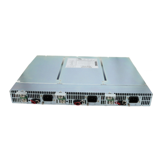
- Page 23 GROUNDING FPS-T1U units are Class I product. To minimize electrical shock hazard, the FPS-T1U units must be connected to an electrical ground. The instruments must be connected to the AC power supply mains through a three conductor power cable, with the ground wire firmly connected to an electrical ground (safety ground) at the power outlet.
- Page 24 AC cables. ENERGY HAZARD Do not connect FPS-T1U units to mains supply exceeding The main outputs of FPS-T1U units are capable of the input voltage and frequency rating. The input voltage and providing hazardous energy. Due to hazardous energy frequency rating is: 100-240V~, 50/60Hz.
-
Page 27: On/Off Control
Up to 1V drop. Twisted pairs In Local sense applications, the +/- sense have to be connected to the +/-Local Sense terminals of the FPS-T1U prior to operating the FPS1000 units plugged in. 2. ON/OFF CONTROL ON/OFF Control_1 ON/OFF Control_2... - Page 28 3. OUTPUT VOLTAG TRIMMING Fig 3-1 shows typical connection for FPS1000 unit ‘A’ inside the rack. Units ‘B’ and ‘C’ connections - Refer to Table 1. FPS1000-12 J1(A) FPS-T1U 0.0324 1.1298 9.9342 J1(A)-8 FPS1000 Module A J1(A)-6 FPS1000-24 V_TRIM J1(A)-7 R1&R2:0.5W...
-
Page 29: Parallel Operation
5.1. Remote sensing and current balance Up to 8 FPS1000 units of the same output voltage rating can be connected in parallel. By connecting the CS signal between FPS-T1U the paralleled units, automatic current balance is achieved, FPS-1000 Module A with +/-10% accuracy. -
Page 30: Fps-T1U I 2 C Bus Interface Option
Note1:Forced air cooling allow minimum 50mm of unrestricted air space at the rear of the unit. Do not obsruct air flow to the unit front panel ADDRESSING (A0, A1, A2). The address line of the FPS1000 units installed in the FPS-T1U rack are internally fixed. Refer to the following table for detailes: Module “A”... - Page 31 The address of each FPS1000 unit is internally fixed. Refer to the addressing table for details. < 80% +/-5% of Vo rated Input voltage < 85Vac...
- Page 32 A/D so that on every read data from each channel is read. Note that on each read. a conversion is started for a particular channel and the result which will be displayed and will be of the previous read. (i.e. the previous channel). Thus second read cycle gives result of the actual channel.
Need help?
Do you have a question about the FPS-T1U and is the answer not in the manual?
Questions and answers