Advertisement
Quick Links
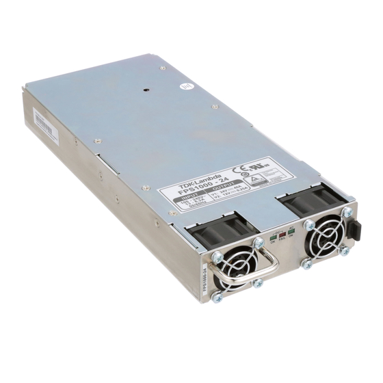
FPS1000 INSTRUCTION MANUAL
FPS1000 SERIES SPECIFICATIONS
1
Rated output voltage
2
Output voltage set point
3
Output voltage range
4
Maximum Output Current (Refer to Fig.1)
5
Maximum output power
6 Input voltage / frequency range
7 Maximum input current (at 100/200Vac)
8
Power Factor (Typ)
9
Efficiency (Typ)
10
Inrush current
11
Hold-up time
12
Maximum line regulation
13
Max load regulation
14
Output Ripple and noise pk-pk
15
Temperature stability
16
Temperature coefficient
17
Remote sensing
18
Parallel operation
19 Series operation
20
Over current protection
21
Over voltage protection
22
Over temperature protection
23
Remote On/Off control
24
DC OK signal
25
Over-Temp. warning
26
AC fail signal
27
Auxiliary power supply
28
Vout voltage trimming
29
Front panel indicators
30
I
2
C Interface
31
Operating temperature-models without IEC inlet
models with IEC inlet
32
Storage temperature
33
Operating humidity
34
Storage humidity
35
Cooling
36
Vibration
37
Shock
38
Conducted emission
39
Radiated emission
40
Applicable safety standards
Withstand voltage
41
42
Insulation resistance
43
Leakage current
44
Weight (Typ)
45
Size (W*H*D)
Notes:
*1: For cases where conformance to various safety standards (UL, EN etc.) is required,
to be described as 100-240Vac (50/60Hz).
*2: At 100/200Vac, rated load and 25˚ C ambient temperature.
*3: Not applicable for the noise filter inrush current less than 0.2mS.
*4: Measured with JEITA RC-9131A 1:1 probe, 20MHz B.W.
*5: From 85~132Vac or 170~265Vac, constant load.
*6: From No-load to Rated load, constant input voltage. Measured at the sensing point in Remote sense.
*7: Remote sensing can compensate up to 1V drop on each load wire.
*8: Inverter shut down method. Reset by AC voltage recycle or by On/Off control.
*9: Derate Maximum output power by 10% for input voltage less than 100V
*10 For FPS 1000-12/P(S), when used not with FPS-S1U or FPS-T1U
racks, an EMI suppressor clamp should be attached to the AC cable,
as close as possible to the AC inlet, to meet class B.
Model
FPS1000
FPS1000
V/I
-12
V1 (V)
12
V2 (V)
13.2
I1 (A)
66
I2 (A)
72
FPS1000-12
V
12
V
12+/-1%
V
10.5~13.2
A
72
W
864
(*1)
---
A
---
(*2)
%
81/83%
(*3)
A
mS
20mS typical at 100Vac input, rated output voltage and less than 80% of rated load.
(*5)
---
(*6)
---
(*4)
mV
150
---
0.05% of rated Vout for 8hrs after 30min warm-up. Constant line, load and temperature.
PPM/°C
(*7)
V
(*9)
---
---
---
(*8)
V
14.3~15.7
---
---
By electrical signal or dry contact. ON: 0~0.6V or short. OFF: 2~15V or open.
Open collector signal. On when Vout ≥ 80+/-5% rated output. Max.sink current: 10mA
---
---
---
---
---
Possible, via Vout Trim pin in the I/O connector. Refer to Instruction Manual. AC OK, DC
---
---
---
0~50°C:100% load. Derate 2%/°C, 50°C to 60°C. Derate 2.5%/°C, 60°C to 70°C
---
---
---
---
---
---
---
---
(*10)
---
---
Input-Output: 3000Vrms, 1min. Input-Ground:
---
More than 100Mohm at 25° C and 70% RH. Output-Ground: 500Vdc
---
mA
Kg
---
FPS1000
FPS1000
-24
-32
-48
24
32
48
29
38.4
58
33
26
17.25
40
31
21
FPS1000-24
FPS1000-32
24
24+/-1%
21.5~29
40
960
85~265Vac continuous, 47~63Hz, Single phase
12.0/6.0
>0.98 at 115/230V and maximum output power
84/86%
Less than 40A
0.40%
0.80%
200
200
Possible. Refer to Instruction Manual.
Possible. Refer to Instruction Manual.
Possible. Refer to Instruction Manual.
105~125% of maximum output current. Refer to Fig. 1
31~34
Inverter shut down method, automatic reset.
Open collector signal. Refer to Instruction Manual
Open collector signal. Refer to Instruction Manual
11.2~12.5VDC. 0.25A Maximum output current.
OK, DC FAIL
Optional. Refer to Instruction Manual.
0~50°C: 100% load. Derate 2%/°C, 50°C to 60°C. -30~85°C
10~90% RH, no condensation.
10~95% RH, no condensation.
By internal Fans. Variable speed control.
Built to meet ETS 300 019
Built to meet ETS 300 019
EN55022B, FCC part 15J-B, VCCI-B
EN55022B, FCC part 15J-B, VCCI-B
UL60950-1, EN60950-1
Vrms, 1min. Output-Ground: 500Vrms,1min.
2000
Less Than 1.1mA at 230Vac
2.0
127x41x290mm. Refer to Outline Drawing.
.
RMS
Vout (V)
V2
V1
Fig. 1: Rated output current vs output voltage
FPS1000-48
32
48
32+/-1%
48+/-1%
28.8~38.4
43~58
31
21
1008
992
84/86%
85/88%
250
300
41.5~45.5
62~66
Iout (A)
I2
I1
Advertisement

Related Manuals for TDK-Lambda FPS1000 Series


Summary of Contents for TDK-Lambda FPS1000 Series
- Page 1 FPS1000 INSTRUCTION MANUAL FPS1000 SERIES SPECIFICATIONS FPS1000-12 FPS1000-24 FPS1000-32 FPS1000-48 Rated output voltage Output voltage set point 12+/-1% 24+/-1% 32+/-1% 48+/-1% Output voltage range 10.5~13.2 21.5~29 28.8~38.4 43~58 Maximum Output Current (Refer to Fig.1) 1008 Maximum output power 6 Input voltage / frequency range...
- Page 4 Missachtung dieser Sicherheitsvorschriften entstehen können. CAUTION: FPS1000 units are not authorized for use as critical component in nuclear control systems, life support systems or equipment for use in hazardous environments without the express written approval of the managing director of TDK-Lambda. Vorsicht: Dieses Produkt ist nicht für die Verwendung als kritische Komponente in nuklearen Steuerungssystemen,...
- Page 5 PARTS SUBSTITUTIONS & MODIFICATIONS Parts substitutions and modifications are authorized TDK Lambda service personnel only. For repairs or modifications, the instrument must be returned to TDK Lambda service facility. AC INPUT Do not connect FPS1000 units to mains supply exceeding the input voltage and frequency rating. The input voltage and frequency rating is: 100-240V~, 50/60Hz.
- Page 7 FPS 1000 CONNECTIONS FOR OPERATION 1. SINGLE UNIT OPERATION Load line. 1.1. Remote sensing* Up to 1V drop. 1,2,4 FPS1000 LOAD SIGNAL 3,5,6 Fig 1-1 Load line. Sense lines Up to 1V drop. Twisted pairs 0.0324 In Local sense applications, the +/- sense have to be connected to the +/-V terminals of the FPS1000 units prior the operating the FPS1000 units FPS1000-12 1.2.
- Page 8 2. PARALLEL OPERA TION 2.1. Remote sensing and current balance Up to 8 FPS1000 units of the same output voltage rating can be connected in parallel. By connecting the CS signal between the paralleled units, FPS1000 #1 automatic current balance is achi e ved, with +/-10% accuracy .
-
Page 9: On/Off
2.3. On/off control On/off control can be made via separate control for individual units (refer to Fig 1-3), or via single control as shown in Fig 2-3. FPS1000 #1 ON/OFF SIG. RETURN FPS1000 #2 ON/OFF SIG. RETURN FPS1000 #N ON/OFF SIG. -
Page 10: Fps1000
4. FRONT PANEL INDICATORS. 1. AC OK Green LED: On when input voltage ≥ 85Vac, Off when Input voltage < 85Vac 2. DC OK Green LED: On when output voltage Vout ≥ 80% +/-5% of Vo rated Off when output voltage Vout < 80% +/-5% of Vo rated 3. -
Page 11: Fps1000
PULL-UP RESISTOR SELECTION Figure 1 shows the internal section of I2C used in FPS series. There are 3 I C ICs. Only one is shown as an example. 22Ω PIN #17 200Ω PIN #18 PIN #13 Fig. 1 Fig. 2 (max) For minimum pullup resistor selection, use the following equation, P (min) -
Page 12: Fps1000
A/D so that on every read data from each channel is read. Note that on each read. a conversion is started for a particular channel and the result which will be displayed and will be of the previous read. (i.e. the previous channel). Thus second read cycle gives result of the actual channel.
Need help?
Do you have a question about the FPS1000 Series and is the answer not in the manual?
Questions and answers