Table of Contents
Advertisement
Quick Links
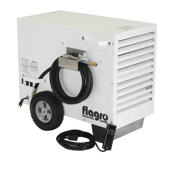
THC 85P
INDUSTRIAL / COMMERCIAL SPACE HEATER
Certified to / Certifié à CGA 2.14 M2000
Conforms to / Conforme à ANSI std Z83.7 2000
Suitable for indoor or outdoor installation / Unvented / Unattended Type
OPERATING INSTRUCTIONS MANUAL
SPECIFICATIONS:
Model .............................................................. THC-85P
Input ............................................................... 85,000
Fuel ................................................................ Propane
Inlet Pressure ................................................... 11" W.C.
Ignition ............................................................ Direct Spark Ignition
Thermostat Control..........................................
Standard
Air Circulation ................................................... 450 cfm
Fuel Consumption .............................................. 4.25 lbs/hr
Approved .......................................................... cETLus listed
Advertisement
Table of Contents

Related Manuals for Flagro THC-85P


Summary of Contents for Flagro THC-85P
- Page 1 Conforms to / Conforme à ANSI std Z83.7 2000 Suitable for indoor or outdoor installation / Unvented / Unattended Type OPERATING INSTRUCTIONS MANUAL SPECIFICATIONS: Model …………………………………………………….. THC-85P Input ……………………………………………………… 85,000 Fuel ………………………………………………………. Propane Inlet Pressure …………………………………………… 11” W.C. Ignition …………………………………………………… Direct Spark Ignition Thermostat Control……………………………………...
-
Page 2: Carbon Monoxide
THC-85P OPERATING INSTRUCTIONS MANUAL GENERAL HAZARD WARNING: FAILURE TO COMPY WITH THE PRECAUTIONS INSTRUCTIONS PROVIDED WITH THIS HEATER, CAN RESULT IN DEATH, SERIOUS BODILY INJURY AND PROPERTY LOSS OR DAMAGE FROM HAZARDS OF FIRE, EXPLOSION, BURN ASPHYXIATION, CARBON MONOXIDE POISONING, AND / OR ELECTRICAL SHOCK. -
Page 3: Installation
WARNING: This heater is designed and approved for use in accordance with Standard ANSI Z83.7- CGA 2.14. CHECK WITH YOUR LOCAL FIRE SAFETY AUTHORITY IF YOU HAVE QUESTIONS ABOUT APPLICATIONS. The intended use of this device is for the temporary heating of buildings or structure under construction, alteration or repair. Other standards govern the use of fuel gases and heat producing products in specific applications. - Page 4 Liquefied Petroleum Gases, ANSI/NFPA 58 and CSA B149.00, Natural Gas and Propane Installation Code. PRESSURES: MAXIMUM INLET PRESSURES: 14.0 IN. WC. MINIMUM INLET PRESSURES: 11.0 IN. WC. This heater must be supplied by pressures indicated on the approval label. Over pressure may cause controls to fail. DO NOT supply this unit with more than 11.0 in.
-
Page 5: Maintenance
DUCTING Manufacturers ducting must be used on this heater. Flagro part number THCP-WD12 (12” x 12 FT Hitex A MAXIMUM OF 12 FT OF DUCTING ONLY POWER SUPPLY INDICATOR LIGHT: The power supply indicator light will help detect any faulty power supplied to the heater such as;... -
Page 6: Start-Up Instructions
START UP INSTRUCTIONS: 1. Connect the POL inlet on the regulator of the heater to the propane cylinder. 2. Open the cylinder valve. 3. Leak test the cylinder connection. 4. Plug in power supply to heater, Visually watch Power Supply Light (See heater label if power is acceptable) 5. - Page 7 THC-85 SERIES TROUBLESHOOTING ANALYSIS PLEASE NOTE: In order to facilitate trouble shooting, unit panels have been removed in some of these pictures for ease of identification only. All panels and fasteners must be in place as provided by the manufacturer to ensure the safe and efficient operation of this gas fuelled appliance. PROBLEM: NO HEAT, FAN OPERATES.
- Page 8 PROBLEM: HEATER WILL NO LIGHT. POSSIBLE CAUSE: Gas Supply. Ensure required gas supply pressures are available to the heater. REMEDY: (see approval label for specifications). POSSIBLE CAUSE: Gas Valve / Solenoid. Ensure solenoid is energized. (use volt meter). REMEDY: Ensure plunder in solenoid is being activated. (use manometer at test point after solenoid). POSSIBLE CAUSE: Igniter / Flame Sensor Ensure the gap between the igniter and sensor is REMEDY:...
- Page 9 PROBLEM: HEATER WILL NOT REMAIN LIT AFTER START UP. POSSIBLE CAUSE: Faulty igniter wire. Check igniter wire for any damage. Replace is necessary. REMEDY: POSSIBLE CAUSE: Faulty igniter / flame sensor. Ensure connections are secure. Replace igniter / flame REMEDY: sensor if necessary.
- Page 10 PARTS DIAGRAM - THC-85 THCP-8510 THCP-8512 THCP-8511 THCP-122 THCP-131 THCP-122 THCP-111 THCP-121 THCP-124 THCP-113/THCP-114A THCP-108A THCP-110 THCP-126A...
- Page 11 THCP-109 THCP-104 THCP-106A THCP-105 THCP-102 THCP-109 THCP-101 THCP-119 THCP-117 (LP) THCP-118 (NG)
- Page 12 PARTS LIST FOR THC-85 Part Number Part Description THCP-101 CAST IRON BURNER THCP-102 IGNITER/ FLAME SENSOR ASSEMBLY THCP-103 IGNITER WIRE THCP-104 120/24 VOLT TRANSFORMER THCP-105 GAS VALVE / SOLENOID - 24V THCP-106A IGNITION CONTROL - 120V THCP-107A WIRING HARNESS FOR THCP-106A THCP-108A HIGH TEMPERATURE LIMIT (OUTLET) CURRENT THCP-109...
- Page 13 ACCESSORIES THCP-WD12 WHITE DUCT 12" X 10FT THCP-DA12 DUCT ADAPTER THCP-DD DUCT DIFFUSER THCP-HD85 HEAT DIFFUSER THCP-TH THERMOSTAT KIT...
- Page 14 THC SERIES WIRING DIAGRAM 2010 HI LIMIT HI LIMIT AIR PROVING SWITCH BURNER SWITCH FAN MOTOR IGNITION CONTROL SWITCH PURPLE BROWN WHITE SMART BLACK INDICATOR YELLOW L1 (BLACK) G (GROUND) N (WHITE) 120v/24v TRANSFORMER IGNITER / FLAME SENSOR GAS VALVE 120 volt 24 volt DATE:...
Need help?
Do you have a question about the THC-85P and is the answer not in the manual?
Questions and answers